Device for simultaneously demonstrating light diffraction effect and mechanical effect
A technology of light diffraction and effect, applied in the field of optics, can solve the problem of not being able to demonstrate the diffraction effect and mechanical effect of light at the same time
- Summary
- Abstract
- Description
- Claims
- Application Information
AI Technical Summary
Problems solved by technology
Method used
Image


Examples
Embodiment 1
[0040] This embodiment 1 demonstrates the diffraction effect of light.
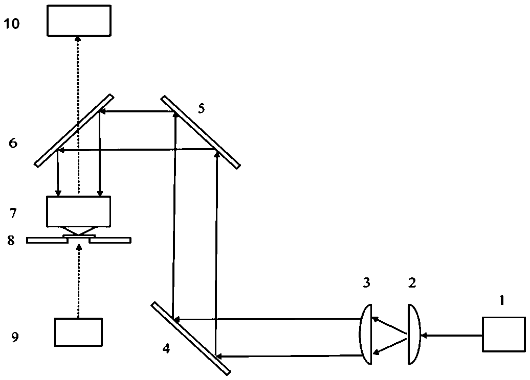
[0041] see figure 1 A device for simultaneously demonstrating light diffraction effects and mechanical effects includes a laser 1, a microscope, and the microscope includes a microscope objective lens 7, a sample cell 11, a stage 8 and an illumination source 9, and the illumination source 9 is located on the stage of the microscope 8 below.
[0042] A first thin lens 2, a second thin lens 3, and a first 45-degree total reflection mirror 4 are arranged in sequence corresponding to the light exit of the laser 1, and a second 45-degree total reflection mirror is arranged corresponding to the first 45-degree total reflection mirror 4 5. Corresponding to the second 45 degree total reflection mirror 5, a dichromatic mirror 6 is provided; the dichromatic mirror 6 is at an angle of 45 degrees, and the light-emitting end of the dichromatic mirror 6 corresponds to the microscopic objective lens 7 of the microscope...
Embodiment 2
[0057] This embodiment 2 demonstrates the mechanical effect of light.
[0058] The overall structure of the experimental device is the same as in Example 1.
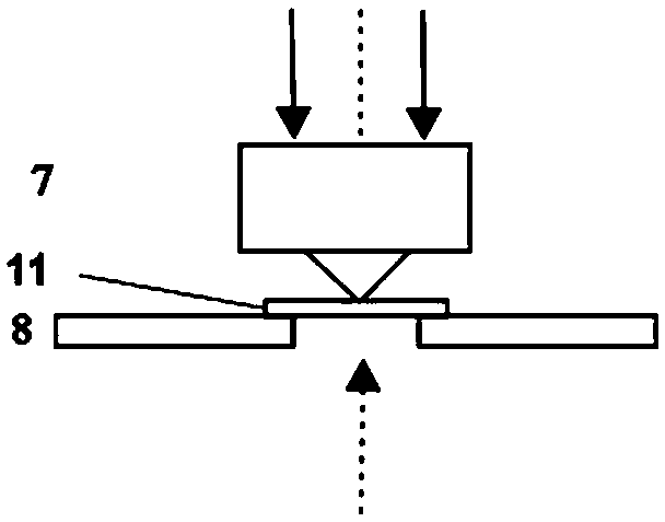
[0059] When being used for the demonstration of the mechanical effect of light, the sample cell 11 is placed on the stage 8, and the suspension of micron balls is placed in the sample cell 11, and the micron balls are polystyrene microspheres with a diameter of 5 microns; see figure 2 , by fine-tuning the microscopic objective lens 7 so that the focal point of the microscopic objective lens 7 is 5 microns away from the bottom surface of the sample cell 11 .
[0060] The fundamental mode Gaussian beam emitted by the laser 1 is expanded by the first thin lens 2 and the second thin lens 3, and the beam is raised by the first 45-degree total reflection mirror 4 and the second 45-degree total reflection mirror 5, and the parallel beam is The dichroic mirror 6 is reflected into the microscopic objective lens 7 of the microsc...
Embodiment 3
[0064] Embodiment 3 simultaneously demonstrates the diffraction effect and the mechanical effect of light.
[0065] The overall structure of the experimental device is the same as in Example 1.
[0066] When used to demonstrate the diffraction effect and mechanical effect of light at the same time, the sample cell 11 is placed on the stage 8, and the suspension of micron balls is placed in the sample cell 11, and the micron balls are polystyrene microspheres with a diameter of 1 micron; The working distance of the microscopic objective lens 7 is 100 microns, and the thickness of the sample pool 11 is smaller than the working distance of the microscopic objective lens 7 .
[0067] The fundamental mode Gaussian beam emitted by the laser 1 is expanded by the first thin lens 2 and the second thin lens 3, and the beam is raised by the first 45-degree total reflection mirror 4 and the second 45-degree total reflection mirror 5, and the parallel beam is The dichroic mirror 6 reflect...
PUM
 Abstract
Description
Claims
Application Information
 - Generate Ideas
- Intellectual Property
- Life Sciences
- Materials
- Tech Scout
- Unparalleled Data Quality
- Higher Quality Content
- 60% Fewer Hallucinations
Browse by: Latest US Patents, China's latest patents, Technical Efficacy Thesaurus, Application Domain, Technology Topic, Popular Technical Reports.
© 2025 PatSnap. All rights reserved.Legal|Privacy policy|Modern Slavery Act Transparency Statement|Sitemap|About US| Contact US: help@patsnap.com