Enhanced vision for driving

Inactive Publication Date: 2007-04-03
SPERO YECHEZKAL EVAN
View PDF15 Cites 295 Cited by
  • Summary
  • Abstract
  • Description
  • Claims
  • Application Information

AI Technical Summary

Benefits of technology

[0015]It is an object of the present invention to provide a new and improved system and method for reducing glare on a vehicle or equipment operator's eyes.
[0016]It is another object of the present invention to provide a new and improved system and method for enhancing a vehicle operator's view of the surrounding environment taking into physical phenomena that would impair the operator's view such as sun glare.
[0017]It is another object of the present invention to provide a new and improved system and method for improving the conditions for a driver to operate a vehicle.
[0018]The invention thus relates to a method and system to enhance the visual performance and alertness of an equipment or vehicle operator and provide data on the operator's location as input to other safety and convenience devices. The method espouses utilizing the minimum number of elements to get the job done while also increasing the reliability and reducing the complexity. As its essential components, the system includes a camera to acquire data of the driver, a computer to analyze the data and a see-through screen to alter what the driver sees.
[0026]In one embodiment of the invention, one or more inward-facing cameras and / or detectors supply data to a computer program which analyzes the location of the driver's eyes, reflections of the eyes and / or where the eyes are looking. If headlights of oncoming vehicles blind the driver, obscuring his view of pedestrians, then pixels on the windshield or clear sun visor or an attachment thereto act as a filter to reduce their intensity. If glare from a mirror is causing discomfort, then either pixels of a film overlying the mirror or on a display screen are activated to block the returned rays, or the mirror itself is actually comprised of a normally reflecting LCD screen and the computer causes the pixels at the glaring location to become temporarily non-reflecting. In addition, it maintains a history to aid in analysis and aids the driver by supplementing his view. That is, if the driver is looking in the mirror and something is blocking his view, then the mirror in addition to, or in place of, becomes a display screen and an enhanced camera view from an additional camera with a view of the rear is substituted for the real view.
[0028]Another advantage of the method is the ability to accurately determine the eye location and the coordinates of the blocking pixels with a minimal amount of calculations. To increase accuracy, a screen raster is used to provide feedback and assure eye location and system performance correctness. In general, the screen raster provides a simplified means for obtaining eye location which has application in numerous eye tracking fields including use with computer displays.

Problems solved by technology

It is difficult for operators of vehicles such as automobiles, buses, trucks, aircraft, trains and boats to see everything around them, especially objects in their path of travel while driving, flying and piloting.
Environmental factors such as the blinding sun or headlights of oncoming or approaching vehicles may interfere with correct visual perception.
For example, a red stoplight may be hard to see against the sun and a fighter pilot will lose sight of enemy aircraft as they fly into the sun.
Headlights, especially those incorrectly aimed or left in high beam mode, are a major source of discomfort in night-time driving.
Oncoming headlight glare is a major cause of driver fatigue and in some instances, the driver is blinded and left unable to see pedestrians or objects in the vehicle's path.
The headlights of following vehicles, especially those installed at higher mounting heights, such as in popular sport utility vehicles, are reflecting at greater intensities off the rearview and side mirrors causing discomfort to many drivers.
This method suffers from the complexity of using two cameras and the intricacy of computational requirements in a rapidly moving and dynamic environment.
This is similar to the Barnes patent (discussed below) and the thought of consumers purchasing no less using such a cumbersome device seems impractical.
There are numerous mechanical and filter material glare shield patents, some with manual and some with automatic positioning, but all will block a general area of the view and not only the glare sources which potentially conceals important information from the driver.
Although an inexpensive detector is now used for the outside glare, this system is only suitable for use with the sun and still uses complex routines to calculate the spatial location of the interior and exterior subjects of interest and the intersection of a ray between them.
This is inconvenient for people who do not wear eyeglasses and are not accustomed to having to wear glasses especially at night and also for people who wear eyeglasses who would have to manage with two apparatus.
The need to find and put on and the possibility of misplacement of such a device make it less practical than today's ready-for-use sun visor.

Method used


Image

  • Enhanced vision for driving
  • Enhanced vision for driving
  • Enhanced vision for driving

Examples


Embodiment Construction

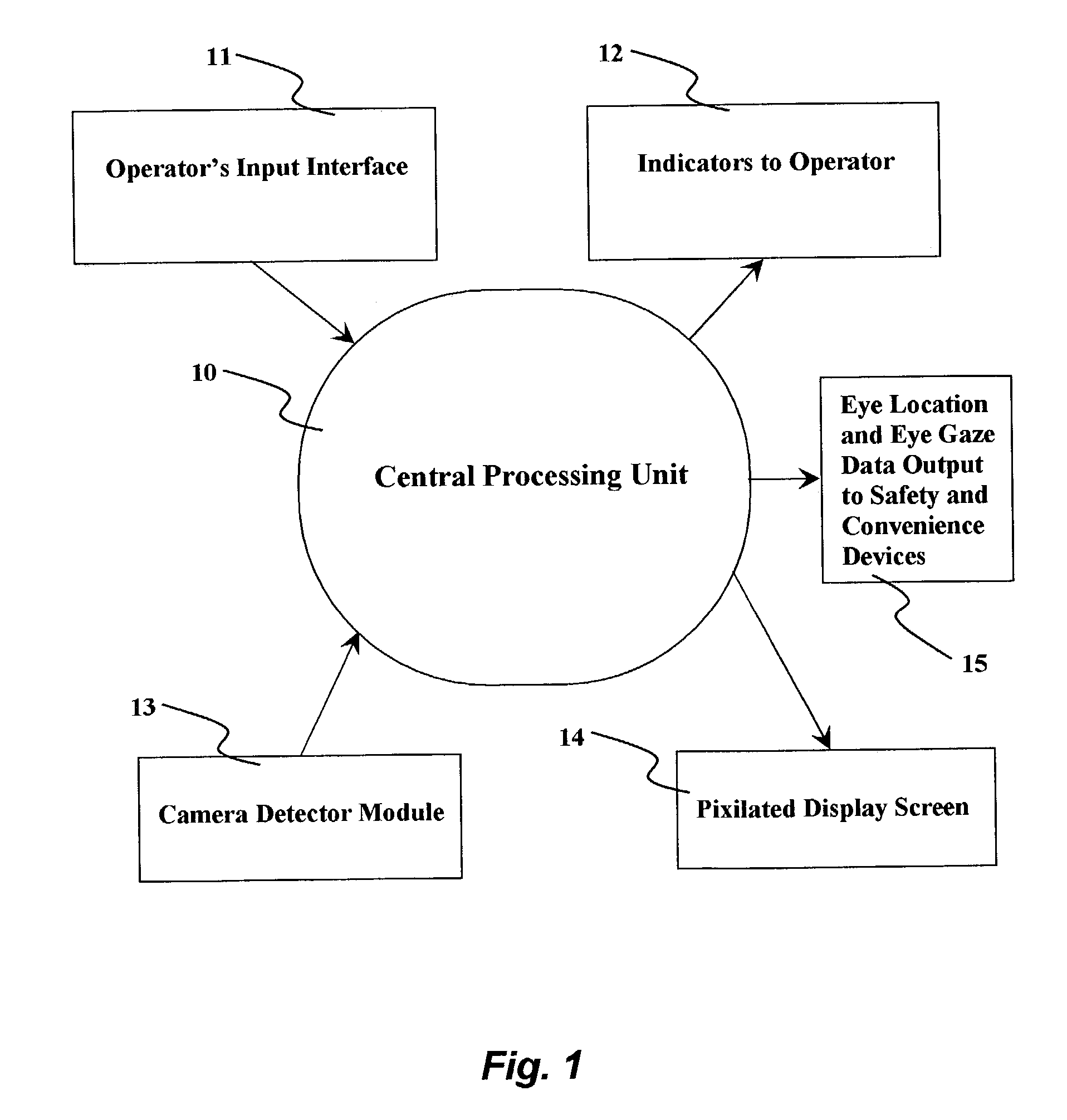
[0039]Referring now to the accompanying drawings wherein like reference numerals refer to the same or similar element, FIG. 1 is a block diagram of an application of the proposed method in an automotive system showing the various input and output devices. A control unit, CPU, DSP, microprocessor, computer, any or all of which are designated as 10, comprised of a logic and memory circuitry receives input signals from the driver, camera / detector unit 13 and optionally other sensors such as temperature sensors.

[0040]The CPU 10 performs analysis of input data and outputs signals to the display screen and / or safety, utility and convenience devices which serve the operator. The computer has a database of parameters, templates and programs. Computer algorithms carry out logical analysis of input data, compare with templates, scenarios and offer information to the driver or other safety and convenience devices. The computer 10 will also perform diagnostics of all system components. The driv...


PUM


Abstract

A system for imposing a filter between a vehicle driver's eyes and a source of light including at least one detector facing inward into a compartment in the vehicle toward a likely position of the head of the vehicle driver and arranged to obtain images of the eyes of the driver and a processor coupled to the detector(s) and arranged to determine the location of the driver's eyes based on analysis of the images obtained by the detector(s) and to obtain information about objects exterior of the vehicle providing sources of light from the images obtained by the detector(s) based on reflections off of the driver's eyes, i.e., the position of such objects. A filter, such as a pixelated screen, is imposed between the sources of light and the driver's eyes based on the location of the driver's eyes and the information about the exterior objects providing the sources of light.

Description

CROSS-REFERENCE TO RELATED APPLICATIONS[0001]The present invention claims priority of U.S. Provisional Patent Application Ser. Nos. 60 / 362,078 filed Mar. 7, 2002 and 60 / 384,845 filed Jun. 4, 2002 which are hereby incorporated by reference in their entirety.FIELD OF THE INVENTION[0002]The invention relates to methods and systems for assisting operators of vehicles to see events and objects in proximity to the vehicle.BACKGROUND OF THE INVENTION[0003]It is difficult for operators of vehicles such as automobiles, buses, trucks, aircraft, trains and boats to see everything around them, especially objects in their path of travel while driving, flying and piloting. Environmental factors such as the blinding sun or headlights of oncoming or approaching vehicles may interfere with correct visual perception. For example, a red stoplight may be hard to see against the sun and a fighter pilot will lose sight of enemy aircraft as they fly into the sun.[0004]Headlights, especially those incorrec...

Claims


Application Information

Patent Timeline
IPC IPC(8): G09G5/00G02B5/20G02B27/00G02B27/01
CPCG02B5/20G02B27/0093G02B27/01B60K35/00G02B2027/014G02B2027/0187G02B2027/0118B60K35/10B60K2360/149
Inventor SPERO, YECHEZKAL EVAN
Owner SPERO YECHEZKAL EVAN
Why Eureka
Try Eureka