
Texturing device and method for polycrystalline silicon wafer

A technology of polycrystalline silicon wafers and silicon wafers, which is applied in chemical instruments and methods, crystal growth, and final product manufacturing, etc., can solve the problems of high color difference, unfavorable uniform reaction of liquid medicine in texturing tank, and insufficient liquid medicine circulation.

Active Publication Date: 2020-10-27
NINGBO ULICA SOLAR SCIENCE & TECHNOLOGY CO LTD
View PDF9 Cites 0 Cited by
  • Summary
  • Abstract
  • Description
  • Claims
  • Application Information

AI Technical Summary

Problems solved by technology

In this way, the reaction of the first half of the cashmere-making tank is severe, and the reaction of the second half of the cashmere-making tank is relatively weak.
In addition, the structure and method of liquid inlet and return pipe arrangement, the distance between the return pipe and the liquid inlet pipe is relatively close, and the internal circulation is carried out nearby, and the circulation of the liquid medicine is very insufficient, which is not conducive to the uniform reaction of the liquid medicine in the entire texturing tank

Method used


Image

  • Texturing device and method for polycrystalline silicon wafer
  • Texturing device and method for polycrystalline silicon wafer

Examples


specific Embodiment 1

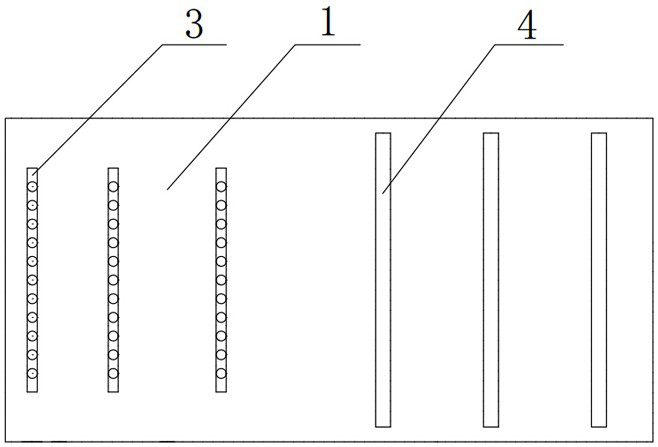
[0031] Specific embodiment one, a polycrystalline silicon wafer texturing device comprises a texturing tank 1, three return pipes 3 are provided at the front half of the bottom of the texturing tank 1, and three liquid inlet pipes 4 are provided at the rear half of the bottom of the texturing tank 1, wherein The liquid inlet pipe 4 is provided with a control valve, and also includes a controller, the control valve is electrically connected to the controller, the return pipe 3 is provided with a return hole, and multiple sets of moving rollers 2 are arranged in the texturing tank 1, and the moving rollers 2. It is divided into upper and lower groups, and the silicon wafers are set in the middle. The silicon wafers are driven to move horizontally in the texturing tank 1 through the upper and lower two groups of moving rollers 2, and liquid blocking wheels 5 are also arranged at both ends of the texturing tank 1. Both ends of the cashmere tank 1 are provided with a first weight de...

specific Embodiment 2

[0033] Specific embodiment two, the main difference with specific embodiment one is that only two return pipes 3 are provided at the front of the cashmere tank 1, and four liquid inlet pipes 4 are provided at the rear, and the liquid inlet flow rate of the liquid inlet pipes 4 is adjusted is 30L / min, and the return hole of the return pipe 3 is a 1 / 3 opening, and the liquid level of the silicon wafer is preferably set to 15-25mm, so that when the liquid level detected by the liquid level detection module is within this range, no It needs to be adjusted. When the liquid level detection module detects that the liquid level is less than 15mm, it is judged that the liquid medicine is too little at this time, and the liquid medicine flow rate of the liquid inlet pipe 4 needs to be increased. At this time, the control valve on the liquid inlet pipe 4 can be adjusted to To increase the flow of liquid medicine, you can also open the previously closed liquid inlet pipe 4 to increase the ...


PUM


Abstract

The present invention relates to the field of solar cell manufacturing technology, and in particular, to a polycrystalline silicon sheet texturing apparatus and method. The apparatus comprises a texturing groove (1) and a moving roller (2) disposed in the texturing groove for driving the movement of the silicon wafer, the bottom of the texturing groove is provided with a return pipe (3) near the entrance position of the silicon wafer, the bottom of the texturing groove is provided with a liquid inlet pipe (4) near the exit position of the silicon wafer, and liquid retaining wheels (5) for blocking the outflow of a chemical solution are provided at the entrance and exit positions of the silicon wafer of the texturing groove. The polycrystalline silicon sheet texturing apparatus and method have a better texturing effect.

Description

Technical field: [0001] The invention relates to the technical field of solar cell preparation, in particular to a texturing device and method for polycrystalline silicon wafers. Background technique: [0002] At present, polysilicon wafer texturing is generally carried out by chain equipment. The silicon wafers travel to the texturing tank and react with the mixed solution of hydrofluoric acid, nitric acid and water to remove the damaged layer introduced by cutting on the surface of the silicon wafer, forming a microscopic layer of about 2um. The pits are the suede surface, which traps light on the surface of the silicon wafer, reduces the reflectivity of the silicon wafer surface, and is beneficial to the improvement of battery efficiency. [0003] The reaction of silicon wafer with hydrofluoric acid and nitric acid is an exothermic reaction, and a large amount of heat is released during the process. The higher the temperature, the more violent the reaction is, and it is a...

Claims


Application Information

Patent Timeline
Patent Type & Authority Patents(China)
IPC IPC(8): H01L31/18H01L31/0236C30B33/10
CPCC30B33/10H01L31/02363H01L31/1804Y02E10/547Y02P70/50
Inventor 蔡二辉刘晓巍徐晓群
Owner NINGBO ULICA SOLAR SCIENCE & TECHNOLOGY CO LTD
Learn More