
Groove-type MOS device and manufacturing method thereof

A technology of MOS devices and manufacturing methods, applied in semiconductor/solid-state device manufacturing, semiconductor devices, electrical components, etc., can solve problems such as limited device structure and manufacturing process, reduce on-resistance, and cannot increase device density, etc., to achieve optimization The effect of manufacturing process, reducing on-resistance, and increasing process difficulty

Active Publication Date: 2018-12-07
CHINA RESOURCES MICROELECTRONICS (CHONGQING) CO LTD
View PDF5 Cites 3 Cited by
  • Summary
  • Abstract
  • Description
  • Claims
  • Application Information

AI Technical Summary

Problems solved by technology

[0006] In view of the above-mentioned shortcomings of the prior art, the object of the present invention is to provide a trench type MOS device and its manufacturing method, which is used to solve the problem that the trench type MOS device in the prior art is limited by its device structure and manufacturing process, Unable to increase device density and reduce on-resistance

Method used


Image

  • Groove-type MOS device and manufacturing method thereof
  • Groove-type MOS device and manufacturing method thereof
  • Groove-type MOS device and manufacturing method thereof

Examples


Embodiment Construction

[0097] Embodiments of the present invention are described below through specific examples, and those skilled in the art can easily understand other advantages and effects of the present invention from the content disclosed in this specification. The present invention can also be implemented or applied through other different specific implementation modes, and various modifications or changes can be made to the details in this specification based on different viewpoints and applications without departing from the spirit of the present invention.

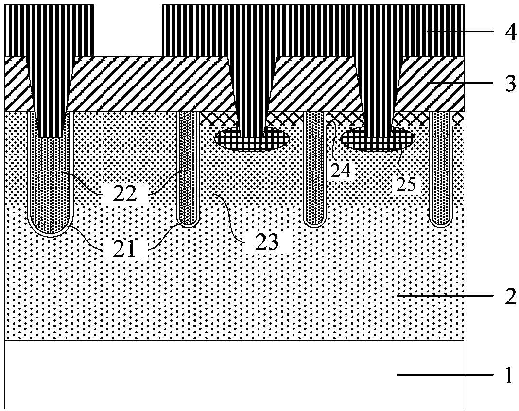
[0098] see figure 2 , the first embodiment of the present invention relates to a trench type MOS device. It should be noted that the diagrams provided in this embodiment are only schematically illustrating the basic idea of ​​the present invention, and only the components related to the present invention are shown in the diagrams rather than the number, shape and shape of the components in actual implementation. Dimensional drawing,...


PUM


Abstract

The invention provides a groove-type MOS (Metal-Oxide-Semiconductor) device and a manufacturing method thereof. The groove-type MOS device at least includes a first conductive heavily doped substrate,a first conductive lightly doped epitaxial layer on the first conductive heavily doped substrate, a plurality of first conductive source regions, a plurality of grooves, a gate oxide layer and a polysilicon gate which are formed in the each groove, a second conductive lightly doped body region formed on the upper portion of the first conductive lightly doped epitaxial layer, a cellular region contact hole formed in the second conductive lightly doped body region, an insulating dielectric block covering the polysilicon gate in the groove of the cellular region, a second conductive heavily doped body contact region formed between two adjacent first conductive source regions of the cellular region, and a metal source electrode formed in the contact hole of the cellular region, wherein the plurality of first conductive source regions and the plurality of grooves are formed on the upper portion of the first conductive lightly doped epitaxial layer at intervals. The groove-type MOS device can guarantee stability of the device while improving the device density and reducing the conduction resistance.

Description

technical field [0001] The invention relates to the technical field of semiconductor manufacturing, in particular to a trench type MOS device and a manufacturing method thereof. Background technique [0002] Trench MOS (Metal-Oxide-Semiconductor, Metal-Oxide-Semiconductor) device is one of the fastest-growing power semiconductor devices with very promising market prospects. It has fast switching speed, high input impedance, and thermal stability. Good performance, high reliability and other advantages, it is widely used in the field of power supply circuits of computers, communication equipment, general office equipment and automotive electronic circuits. [0003] On-resistance is an important parameter to determine the maximum output power and on-state loss of trench MOS devices, expressed in Ron. With the continuous improvement of application field requirements, or the constant pursuit of profit maximization, it is necessary to continuously reduce the on-resistance per un...

Claims


Application Information

Patent Timeline
IPC IPC(8): H01L29/78H01L21/336H01L29/06H01L29/423
CPCH01L29/0684H01L29/4236H01L29/66515H01L29/78
Inventor 蒋正洋
Owner CHINA RESOURCES MICROELECTRONICS (CHONGQING) CO LTD
Learn More