Engine waste heat utilization system based on bionic uniform heating plate and pulsating heat pipe phase change heat storage technology

A phase change heat storage and pulsating heat pipe technology, applied in engine components, combustion engines, machines/engines, etc., can solve the problems of heat loss in the cooling system and exhaust system, shortening engine life, difficult to start the engine, etc., so as to prolong the life. , the effect of reducing wear and speeding up the starting speed

Active Publication Date: 2018-12-07
XIANGTAN UNIV
View PDF5 Cites 2 Cited by
  • Summary
  • Abstract
  • Description
  • Claims
  • Application Information

AI Technical Summary

Problems solved by technology

[0003] In the cold winter, due to the low external ambient temperature, it is difficult to start the engine, the engine wear will be aggravated during the start process, and the life of the engine will be shortened; the external engine preheating device needs to consume additional energy. The waste heat engine system uses the energy discharged from the cooling system for engine preheating, which can not only solve the problem of heat loss in the cooling system and exhaust system, improve energy utilization efficiency, but also realize engine preheating, making it easier for the car to operate in a low temperature environment. to start

Method used


Image

  • Engine waste heat utilization system based on bionic uniform heating plate and pulsating heat pipe phase change heat storage technology
  • Engine waste heat utilization system based on bionic uniform heating plate and pulsating heat pipe phase change heat storage technology
  • Engine waste heat utilization system based on bionic uniform heating plate and pulsating heat pipe phase change heat storage technology

Examples


Embodiment Construction

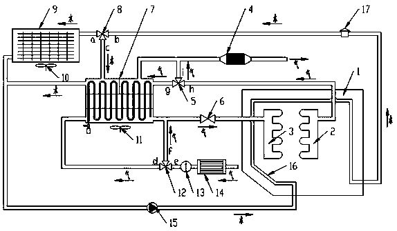
[0019] Such as figure 1 As shown, the engine waste heat utilization system based on bionic vapor chamber and pulsating heat pipe phase change heat storage technology is characterized in that it is composed of engine 1, cooling system, air intake system and exhaust system; the cooling system is composed of engine block cooling water jacket 16. Temperature sensor 17, water pump 15, fan I 10, fan II 11, radiator 9, pulsating heat pipe phase change accumulator 7, cooling system three-way valve 8, air intake system consists of air filter 14, air flow meter 13 , intake manifold 3, intake system three-way valve 12, intake valve 6 and cylinder; exhaust system consists of exhaust manifold 2, exhaust hose, catalytic converter 4 and exhaust system three-way valve 5 composition.

[0020]In a cold environment, hot water flows out from the cylinder cooling water jacket 16 during the operation of the engine 1, and the temperature sensor 17 monitors the water temperature. The three-way valve...


PUM


Abstract

The invention discloses an engine waste heat utilization system based on a bionic uniform heating plate and pulsating heat pipe phase change heat storage technology. A pulsating heat pipe phase changeheat accumulator based on the bionic uniform heating plate and pulsating heat pipe phase change heat storage technology is additionally installed in a cooling system. The device adopts the bionic uniform heating plate and pulsating heat pipe phase change heat storage technology, and the internal space of the device is partitioned. Cooling water and the waste heat in exhaust gas can be absorbed and stored in a water cooling region, a gas cooling region and a phase change heat storage region, the cold air is preheated in a gas preheating region, and therefore starting of an engine in a cold environment is facilitated. A bionic uniform heating plate, pulsating heat pipe and carbon nano tube paraffin phase change heat storage material in the device has an enhanced heat transfer effect, greatly improves the heat dissipation efficiency, enables heat transfer to be uniform, and avoids the phenomenon of local overheating. By the adoption of the engine waste heat utilization system, comprehensive utilization of the engine waste heat is achieved, the energy utilization rate is improved, and the purposes of saving resources and protecting the environment are achieved.

Description

technical field [0001] The invention belongs to the field of power machinery, and in particular relates to an engine waste heat utilization system based on bionic vapor chamber and pulsating heat pipe phase change heat storage technology. Background technique [0002] According to the evaluation of existing internal combustion engine indicators, about 60% of the energy in fuel oil has not been effectively utilized, and most of it is discharged into the atmosphere in the form of waste heat, causing huge economic losses and serious environmental pollution. The waste heat of the car is mainly discharged in two ways: the first is the water circulation of the cooling system to dissipate heat, and the second is the exhaust system to dissipate heat through the vehicle exhaust. A large amount of high-temperature waste heat is directly discharged into the atmosphere, causing heat loss and environmental pollution. pollution. If these two parts of heat can be stored and utilized while...

Claims


Application Information

Patent Timeline
Patent Type & Authority Applications(China)
IPC IPC(8): F02G5/04F02M31/04
CPCF02G5/04F02M31/04Y02T10/12
Inventor 张建平胡慧瑶龚曙光吴淑英李云迪刘庭显
Owner XIANGTAN UNIV
Why Eureka
Try Eureka