
Controller for non-complementary active clamp flyback converter

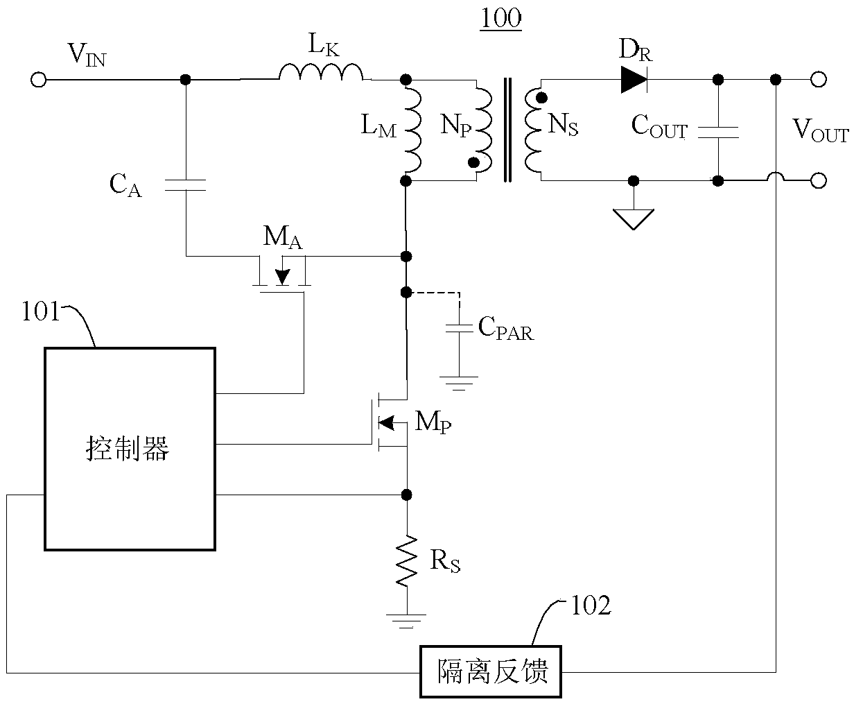
A flyback converter, non-complementary technology, used in control/regulation systems, conversion of DC power input to DC power output, instruments, etc., can solve problems such as difficulty in optimizing efficiency and limited frequency reduction range of converters

Active Publication Date: 2018-12-04
SHENZHEN NANYUN MICROELECTRONICS CO LTD +1
View PDF2 Cites 27 Cited by
  • Summary
  • Abstract
  • Description
  • Claims
  • Application Information

AI Technical Summary

Problems solved by technology

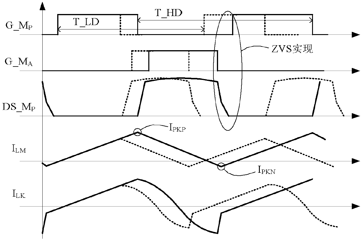
When using the peak current loop control mode, the frequency reduction range of the converter is limited, often only half of the maximum frequency, so that the efficiency from light load to no load is difficult to optimize

Method used


Image

  • Controller for non-complementary active clamp flyback converter
  • Controller for non-complementary active clamp flyback converter
  • Controller for non-complementary active clamp flyback converter

Examples


Embodiment 1

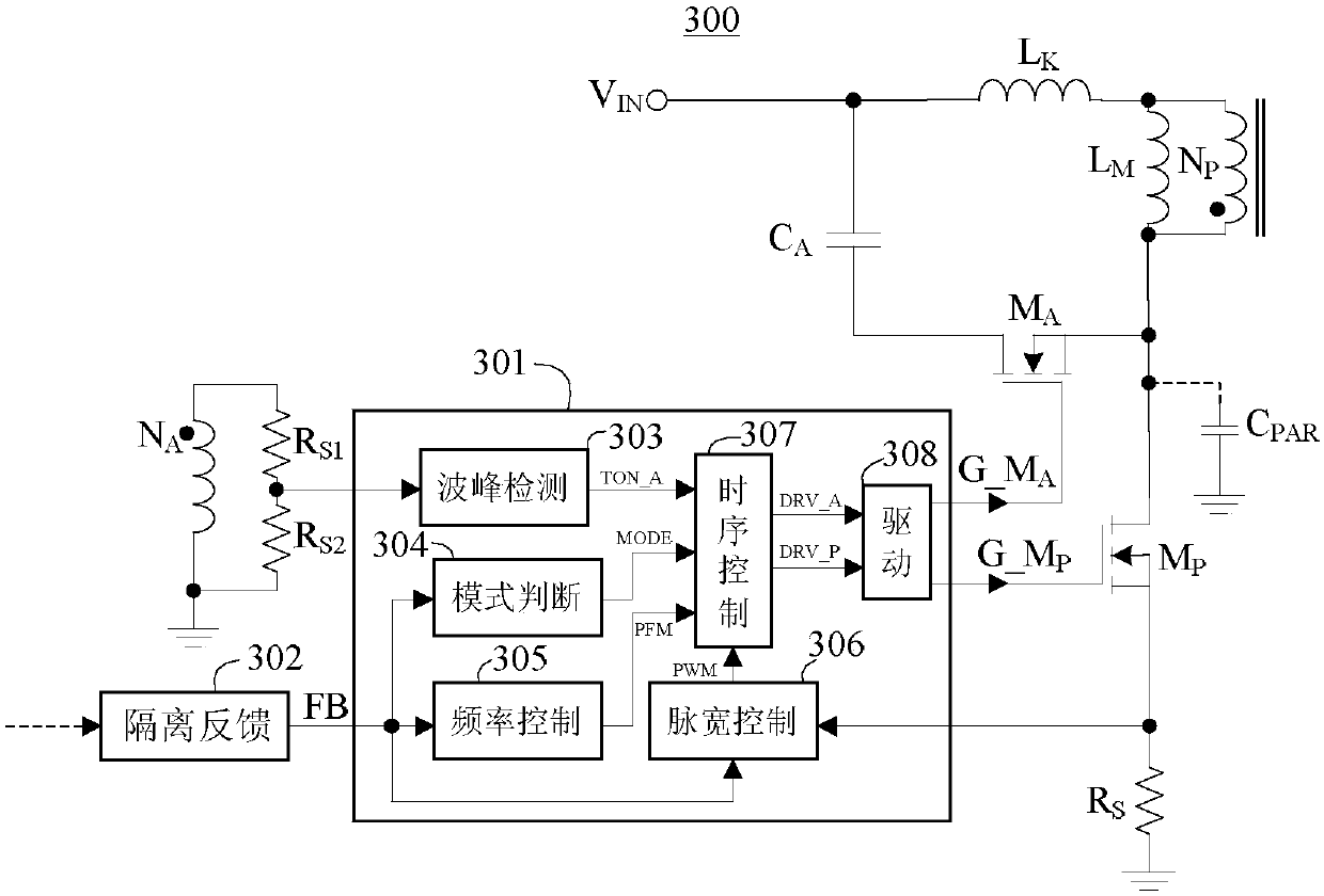
[0034] like Figure 4 As shown, it is an embodiment of a peak detection unit, a peak detection unit 400, including a comparator 401, a reference voltage 402, a current source 403, a PMOS transistor 405, an NMOS transistor 404, a capacitor 406, a Schmitt trigger 407, Inverter 408. The positive input terminal of 401 is connected to the voltage dividing node of the auxiliary winding, the negative terminal is connected to 402, the output terminal of 401 is connected to the gate terminals of 404 and 405; the source terminal of 405 is connected to the output terminal of 403, and the drain terminal is connected to The drain terminal of 404, the upper plate of 406 and the input terminal of 407; the input terminal of 403 is connected to the internal power supply V CC ; The source terminal of 404 is grounded, and the lower plate of 406 is grounded; the output terminal of 407 is connected to the input terminal of 408; 408 gives the clamp tube turn-on signal TON_A. When the switching nod...

Embodiment 2

[0038] like Figure 5Shown is another embodiment of the peak detection unit, a peak detection unit 500, including an inflection point detection circuit 501, a reference voltage 502, a comparator 503, an RS flip-flop 504, a narrow pulse generator 505, a current mirror 506, a switch 507, a switch 508, a capacitor 509, a capacitor 510, a switch 511, a comparator 512, and a D flip-flop 513. The input terminal of 501 and the negative input terminal of 503 are connected to the voltage dividing node of the auxiliary winding voltage, and the output terminal of 501 is connected to that of 504 Set terminal; the positive input terminal of 503 is connected to 502, the output terminal is connected to the reset terminal of 504 and the input terminal of 505; the Q output terminal of 504 is connected to the control terminal of 507; the output terminal of 505 is connected to the control terminal of 511; 506 outputs the first One current I CH1 To one end of 507, output another current I CH2 T...


PUM


Abstract

The invention provides a controller for a non-complementary active clamp flyback converter. The controller comprises a frequency control unit, a pulse width control unit, a sequential control unit anda driving unit, uses a multi-mode control mode, and further comprises a wave peak detecting unit and a mode a determining unit. The wave peak detecting unit detects the peaks of an oscillating voltage at the drain end of a main switching tube, and turns on a clamp tube at the troughs in the non-complementary mode of the converter. The turning off of the clamp tube is determined by internally setturn-on time. The mode determining unit, according to feedback voltage FB, gives a mode switching signal to the sequential control unit according to a mode determining result signal. By using a DCM mode, the controller prevents the clamp tube from being turned on, reduces the peak-to-peak value of the excitation current when entering a frequency hopping mode, avoids audio noise, and optimizes no-load power consumption. Since the comparison process of the mode conversion is provided with a long time delay, the influence of mode switching on a converter control loop is reduced.

Description

technical field [0001] The invention relates to an active clamp flyback converter, in particular to a controller of a non-complementary active clamp flyback converter. Background technique [0002] Flyback converters are widely used in small and medium power off-line switching power supplies due to their low cost and simple topology. In the actual working process, the energy of the primary side of the flyback converter cannot be completely transferred to the secondary side, and the energy left on the primary side is resonated at the switching node, that is, the drain end of the main switching tube, through the leakage inductance and the parasitic capacitance of the switching node. Very high voltage spikes. In order to reduce the voltage stress of the switch tube, a snubber circuit is needed. Conventional snubber circuits include RCD clamping circuits, LCD clamping circuits and active clamping circuits. Among them, the active clamping circuit adds an additional clamping tub...

Claims


Application Information

Patent Timeline
Patent Type & Authority Applications(China)
IPC IPC(8): H02M3/335
CPCH02M3/33569H02M1/0058Y02B70/10
Inventor 於昌虎肖华曾正球
Owner SHENZHEN NANYUN MICROELECTRONICS CO LTD
Learn More