High efficiency heat dissipation power amplifier manufacturing method and heat dissipation cabinet

A technology of a power amplifier and a manufacturing method, which is applied in cooling/ventilation/heating transformation, chassis/cabinet/drawer parts, electrical equipment structural parts, etc. High resistance, inability to spread the power amplifier chip, etc., to achieve the effect of reducing grounding resistance, reducing weight and volume, and reducing volume and weight

Inactive Publication Date: 2018-11-23
NO 54 INST OF CHINA ELECTRONICS SCI & TECH GRP
View PDF7 Cites 1 Cited by
  • Summary
  • Abstract
  • Description
  • Claims
  • Application Information

AI Technical Summary

Problems solved by technology

[0003] In this case, the grounding resistance of the power amplifier chip is high, and the traditional power amplifier design is too long due to the thermal conduction link and the existence of several layers of contact thermal resistance, resulting in the overall thermal conduction resistance of the power amplifier being too high
[0004] As the heat flux density of the power amplifier chip is getting higher and higher, while the structure of the power amplifier chassis is required to be more and more compact, the traditional power amplifier has been unable to effectively spread the heat loss generated by the power amplifier chip to the surrounding environment, resulting in the overall temperature gradient of the power amplifier. If it is too large, the junction temperature of the power amplifier chip will be too high, which will seriously affect the power discharge performance and even affect the service life of the power amplifier

Method used


Image

  • High efficiency heat dissipation power amplifier manufacturing method and heat dissipation cabinet
  • High efficiency heat dissipation power amplifier manufacturing method and heat dissipation cabinet
  • High efficiency heat dissipation power amplifier manufacturing method and heat dissipation cabinet

Examples


Embodiment Construction

[0030] In order to make it easier for those skilled in the art to understand the technical solution of this patent, and at the same time, in order to make the technical purpose, technical solution and beneficial effect of this patent clearer, and to fully support the protection scope of the claims, the following is a specific case in the form of this patent. The technical solution of the patent makes further and more detailed descriptions.

[0031] A method for manufacturing a high-efficiency heat dissipation power amplifier, comprising the following steps:

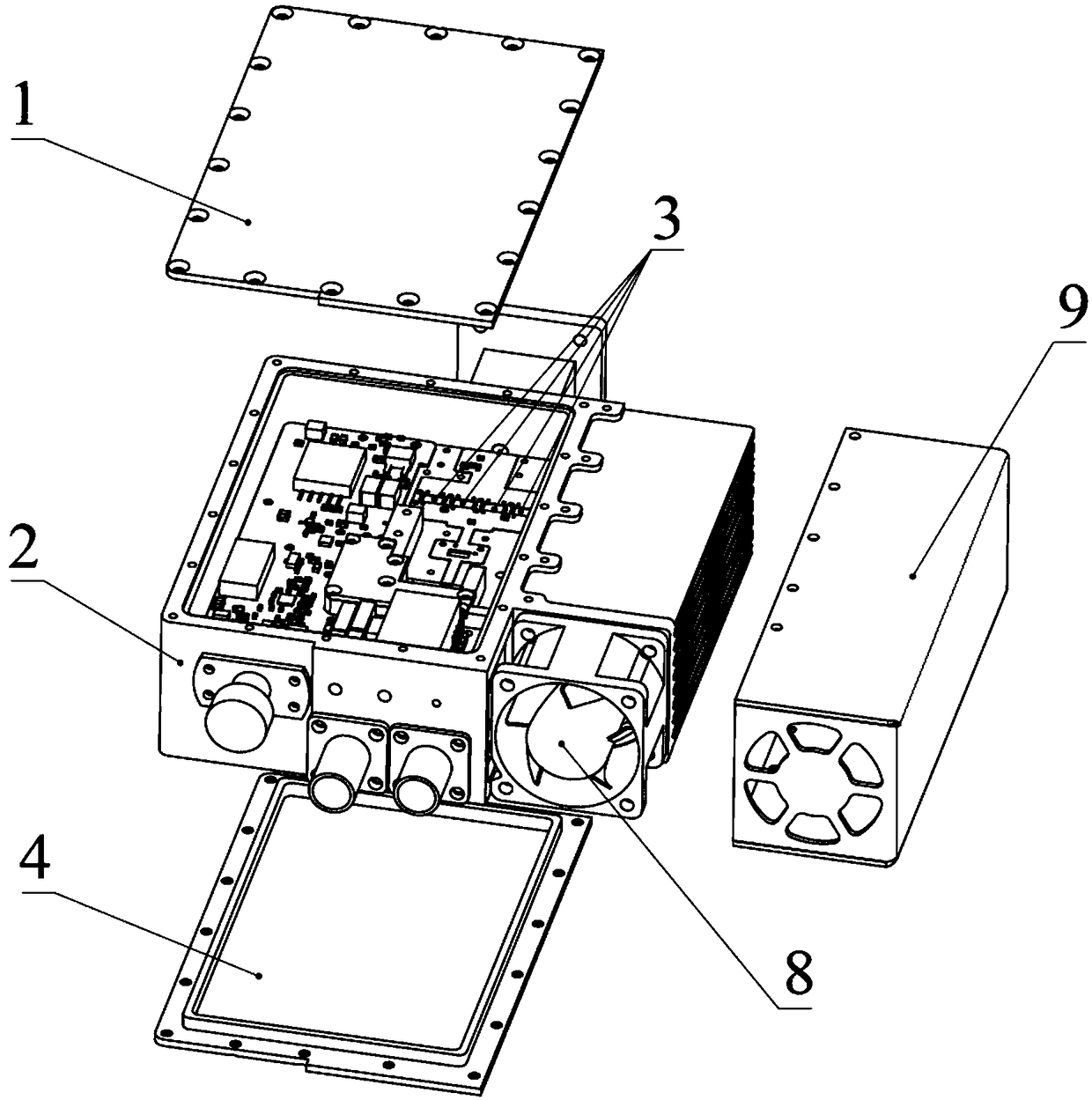
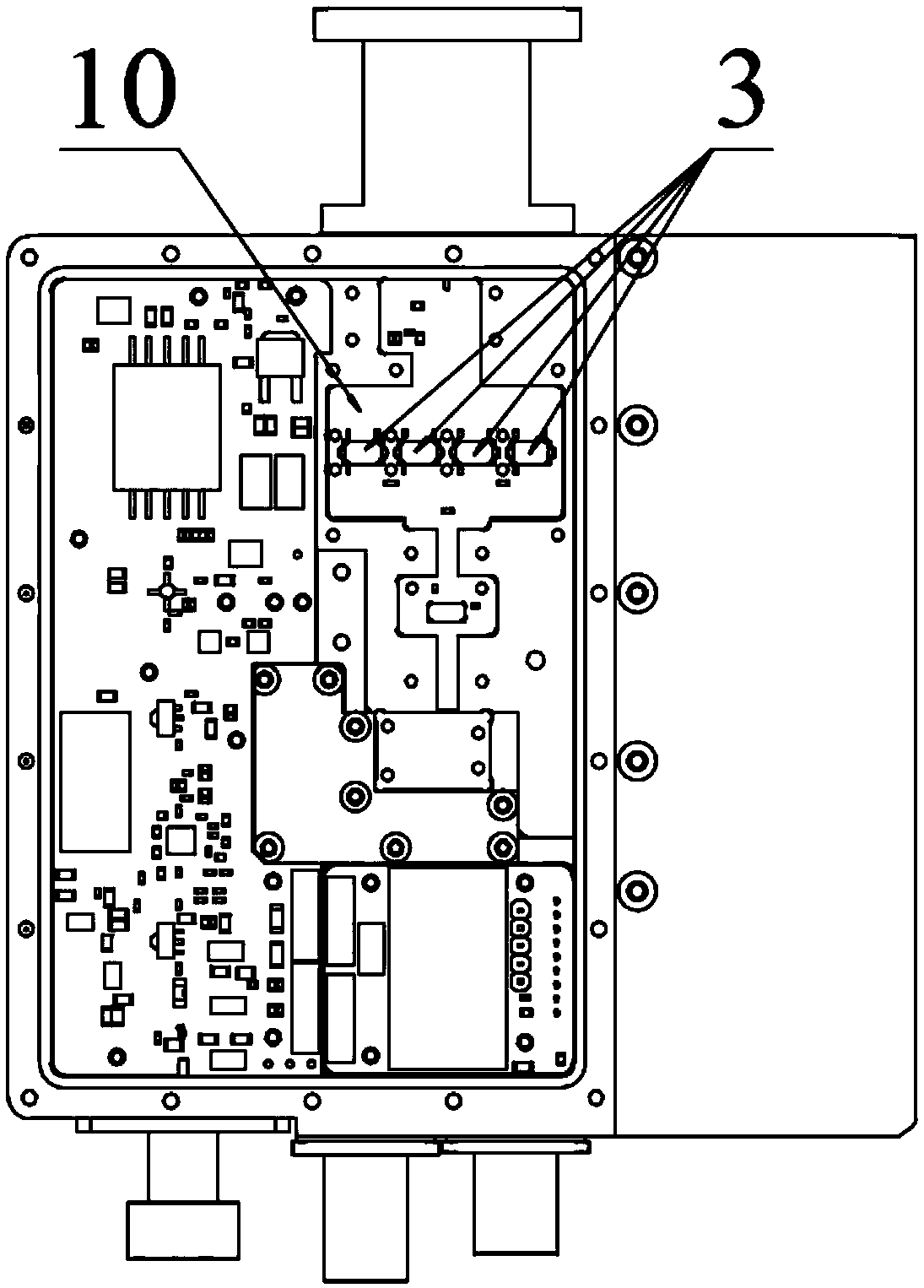
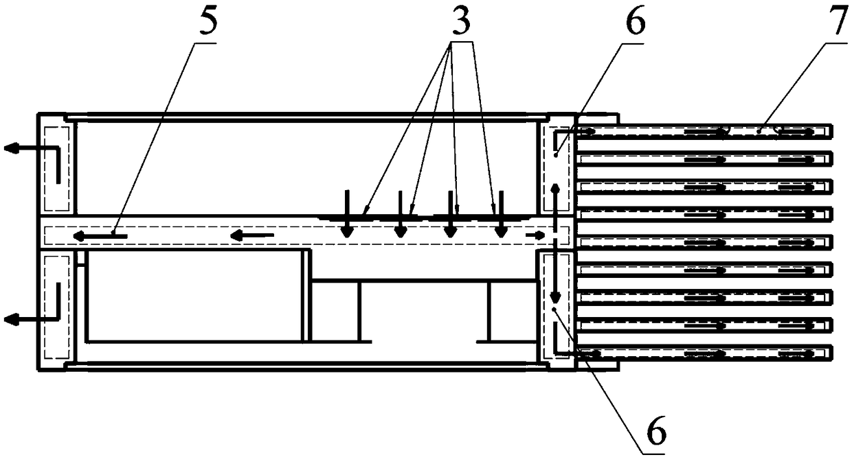
[0032] (1) Prepare the plate as the box wall and heat dissipation fins, weld the box wall to form a heat dissipation chassis, and weld the heat dissipation fins to the outside of the heat dissipation chassis; there are one or more device cavities inside the heat dissipation chassis, and at least one device cavity is a power amplifier Cavity;

[0033] (2) Mill one or more chip mounting slots on the bottom wall of the powe...


PUM


Abstract

The invention provides a high efficiency heat dissipation power amplifier manufacturing method and a heat dissipation cabinet, which belongs to the technical field of microwave power amplifier. The common partition wall, the side walls of the cabinet, and all the fins are welded together to form an integrated heat dissipation cabinet for the power amplifier, and the MMIC bare chip of the power amplifier is directly sintered to the common partition wall of the heat dissipation cabinet. According to the high efficiency heat dissipation power amplifier manufacturing method and the heat dissipation cabinet, the method can effectively reduce the temperature gradient of the power amplifier and the grounding resistance of a power amplifier chip, improve the reliability of the power amplifier, andis suitable for solving the heat dissipation problems of the power amplifier with small volume, light weight, and high heat flux density as an important improvement to the prior art.

Description

technical field [0001] The invention relates to the technical field of microwave power amplifier manufacture and heat dissipation, in particular to a method for manufacturing a power amplifier with high heat dissipation and a heat dissipation chassis. Background technique [0002] At present, in the field of microwave power amplifiers, the traditional power amplifier chip must be packaged in the shell first, and then the packaged chip is sintered into the power amplifier module of the space power synthesis, and the power amplifier module is then fastened to the heat dissipation chassis together with the thermal pad. [0003] In this case, the grounding resistance of the power amplifier chip is high, and the traditional power amplifier design has too long thermal conduction link and the existence of several layers of contact thermal resistance, resulting in too high overall conduction thermal resistance of the power amplifier. [0004] As the heat flux density of the power ...

Claims


Application Information

Patent Timeline
Patent Type & Authority Applications(China)
IPC IPC(8): H05K7/20H05K5/02H05K7/14
CPCH05K5/0217H05K7/1424H05K7/20418
Inventor 薛腾卫少卿寇阳
Owner NO 54 INST OF CHINA ELECTRONICS SCI & TECH GRP
Why Eureka
Try Eureka