
Silicon-based electro-absorption modulator and preparation method thereof

An electro-absorption modulator, silicon-based technology, applied in the field of optical interconnection, can solve the problems of complex manufacturing process, complex process, small process tolerance, etc., achieve high modulation efficiency, eliminate dependencies, and improve process tolerance. Effect

Active Publication Date: 2018-11-16
INST OF SEMICONDUCTORS - CHINESE ACAD OF SCI
View PDF4 Cites 5 Cited by
  • Summary
  • Abstract
  • Description
  • Claims
  • Application Information

AI Technical Summary

Problems solved by technology

The structure proposed by the University of Ghent requires selective etching of silicon, chemical mechanical polishing is required after the epitaxy of silicon germanium, and an optical coupler (taper) structure is made, and the process is relatively complicated; the structure proposed by Huawei requires PN junctions to be fabricated On silicon, germanium is directly selected for epitaxy on silicon, and no subsequent etching or thinning process is required. However, since the PN junctions are all made on silicon, there is a potential barrier at the silicon-germanium interface, and the distributed electric field in germanium is very weak, requiring a large The bias voltage can only work, and because there is no taper structure, the insertion loss of the device is very sensitive to the length of the modulation layer, and the process tolerance is small; and the structure of the vertical PIN junction proposed by the Institute of Semiconductors, Chinese Academy of Sciences is also more complicated. Sub-growth, etching and doping processes, and in order to make n ++ Si is easy to manufacture, and the silicon germanium modulation layer is wider, resulting in a multi-mode modulation layer, which affects communication capacity and transmission distance

Method used


Image

  • Silicon-based electro-absorption modulator and preparation method thereof
  • Silicon-based electro-absorption modulator and preparation method thereof
  • Silicon-based electro-absorption modulator and preparation method thereof

Examples


Embodiment Construction

[0039] In order to make the object, technical solution and advantages of the present invention clearer, the present invention will be described in further detail below in conjunction with specific embodiments and with reference to the accompanying drawings.

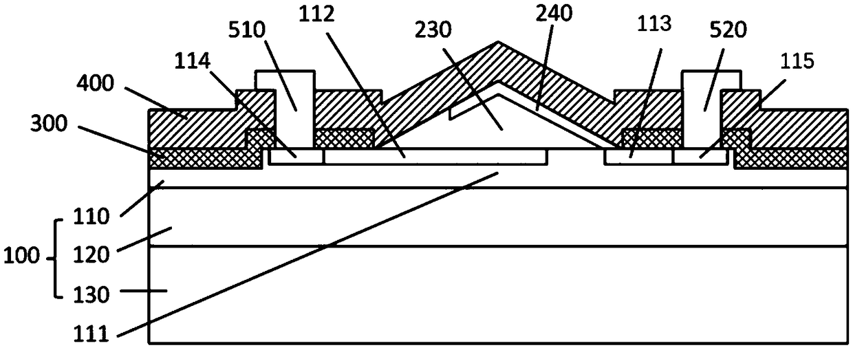
[0040] figure 1 , figure 2 Shown are the three-dimensional structure schematic diagram and the cross-sectional schematic diagram of the silicon-based electro-absorption modulator of the present invention, it can be seen that the silicon-based electro-absorption modulator includes the following parts: SOI substrate 100, doped layer, silicon dioxide window layer 300 , modulation layer 200, insulating medium layer 400 and electrodes.

[0041]SOI substrate 100: the substrate is composed of three parts, from bottom to top are the bottom Si material layer 130, the silicon dioxide buried layer 120 and the top layer of silicon 110, and then engraved on the top layer of silicon 110 of the substrate 100 There is a waveguide laye...


PUM


Abstract

The invention provides a silicon-based electro-absorption modulator and a preparation method thereof. The modulator uses voltage to adjust the light absorption coefficient of a semiconductor on the basis of an electro-absorption mode, and then the intensity of an optical signal is adjusted. Silicon is a weak electro-optical material, so that the silicon is introduced into material germanium whichhas a remarkable electro-optical absorption adjusting effect in a communication wave band C wave band and is compatible with the CMOS technology. Through an epitaxial growth modulation layer (200), light beams are smoothly coupled into and coupled out of the modulation layer (200), oscillation of light field power of the light beams between the modulation layer and a waveguide layer is not generated, the dependence relation between the insertion loss of a device and the length of the modulation layer is eliminated, meanwhile, different working wavelengths can be achieved by adjusting alloy components in the modulation layer (200), and the modulation efficiency is high.

Description

technical field [0001] The invention relates to the field of optical interconnection, in particular to a silicon germanium electric absorption modulator. Background technique [0002] With the continuous development of integrated circuits and the continuous improvement of integration density, traditional electrical interconnection has become the main bottleneck for performance improvement, mainly manifested in: delay increase, power consumption increase, and signal crosstalk increase. Due to the characteristics of high speed, high bandwidth and low power consumption of optical interconnection, on-chip optical interconnection based on silicon-based photonic devices is expected to solve the limitation of traditional electrical interconnection on the development of integrated circuits. Among them, the silicon-based electro-optic modulator is one of the key devices for silicon-based optical interconnection, and it is also an important research topic in recent years. There are t...

Claims


Application Information

Patent Timeline
IPC IPC(8): G02F1/015G02F1/025
CPCG02F1/015G02F1/025G02F1/0157
Inventor 刘智成步文薛春来
Owner INST OF SEMICONDUCTORS - CHINESE ACAD OF SCI
Learn More