


Quick Research
Generate reliable direction feasibility study reports for your R&D in just a few steps.

Technical Q&A
Discover and master advanced knowledge NOW. Basics, ideas, possibilities, all at once.

Find Solutions
As an expert in R&D theories, this can generate solutions to your technical problems instantly.

Evaluate Feasibility
Analyze your overall solution with one click, know your potential R&D risks in advance.

Monitor Landscape
Get weekly tech updates, stay abreast of the latest tech innovations and key insights.
Heat pipe and heat storage combined type water cooling method and device thereof
A combined and heat storage technology, applied in water shower coolers, heat exchanger types, lighting and heating equipment, etc., can solve the corrosion of piping systems and cooling equipment, increase the corrosion of circulating water, and breed bacteria and algae and other issues, to achieve the effects of energy saving, water resistance, reduction of latent heat evaporation loss, and elimination of pollution
- Summary
- Abstract
- Description
- Claims
- Application Information
AI Technical Summary
Problems solved by technology
Method used
Image

Examples
Embodiment 1
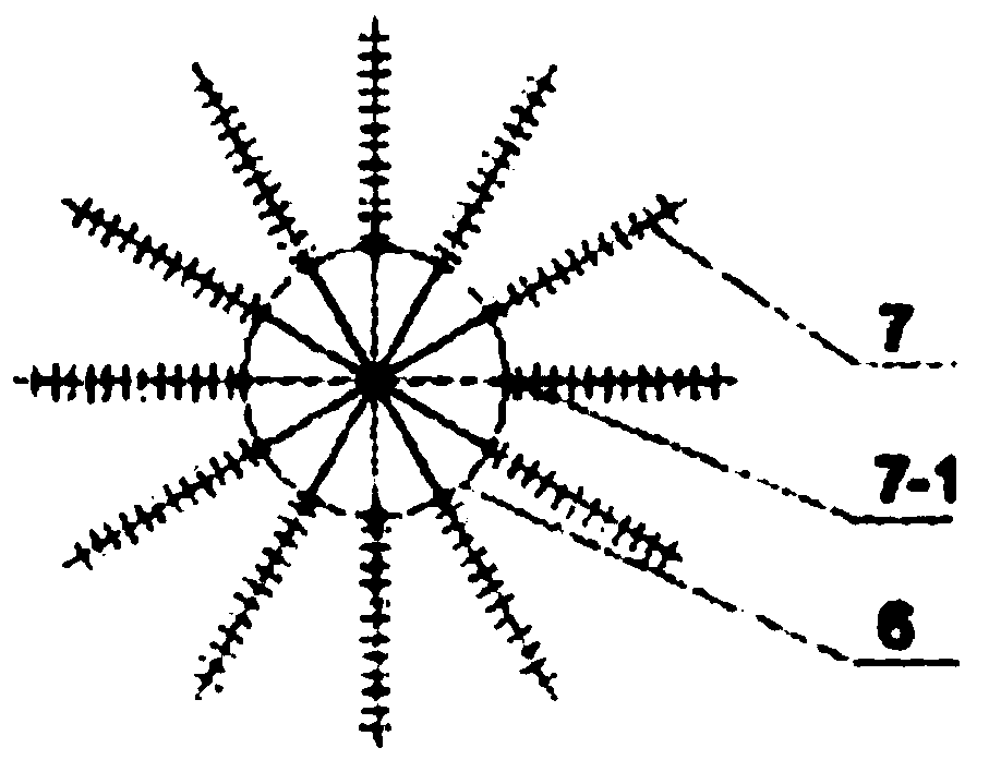
[0021] Embodiment one: if figure 1 As shown, the heat storage rotary cooling tower includes a support device 2 at the bottom of the shell 1, and the support device 2 is transparent in a grid shape. The heat storage body 3 supported on the support device 2 is a rotating disc, and the disc is installed on the on the central axis 8, and can be driven along the axis by the drive device 19 to rotate along the axis to form the rotation of the regenerator 3 rotating disc. The drive device 19 can be installed on the axis or outside the disc shaft. The top of the plate is divided into two parts, one part is the circulating water circulation part, and the other is the cooling air circulation part; the circulating water from the circulating water pipe 6 flows into the terminal water flow distributor 4, and the uniform water flow distributor 4 can distribute the circulating water The water flows out uniformly in a large area in the radial direction, and the water flow through the distribu...
Embodiment 2
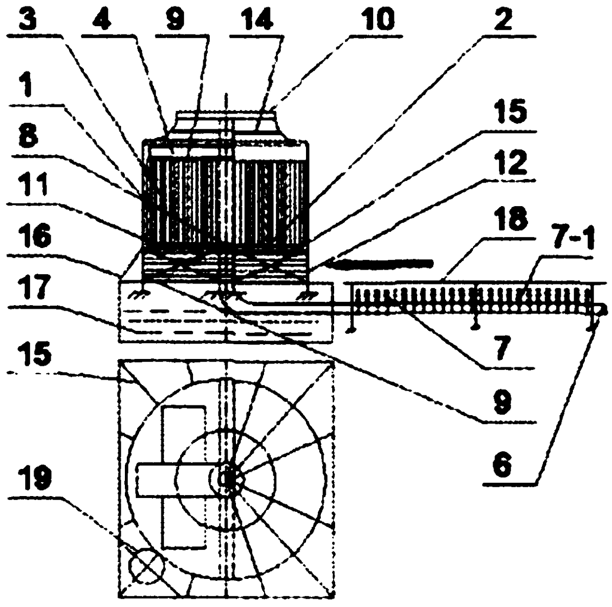
[0022] Embodiment two: if figure 2 As shown, the over-flow cooling tower includes a support device 2 at the bottom of the shell 1, and the support device 2 is transparent in a grid shape. The heat storage body 3 supported on the support device 2 is a box type, and the heat storage body 3 is up and down. Transparent, the distributor 4 is located above the box body, when the heat storage body 3 box moves forward along the track 13 and passes through the outlet water flow of the distributor 4, the water flow falls into the water inlet 9 and fully meets the heat storage body in the heat storage body 3 box body. Contact, flow into the receiving pool or circulating pool 17 below through the water outlet 11, and the heat storage body 3 box continues to move forward along the track 13. When the heat storage body 3 box body passes through the cooling air area, its upper and lower ports are respectively cooling. Air inlet 12 and cooling air outlet 10, the cooling air flows through the ...
Embodiment 3
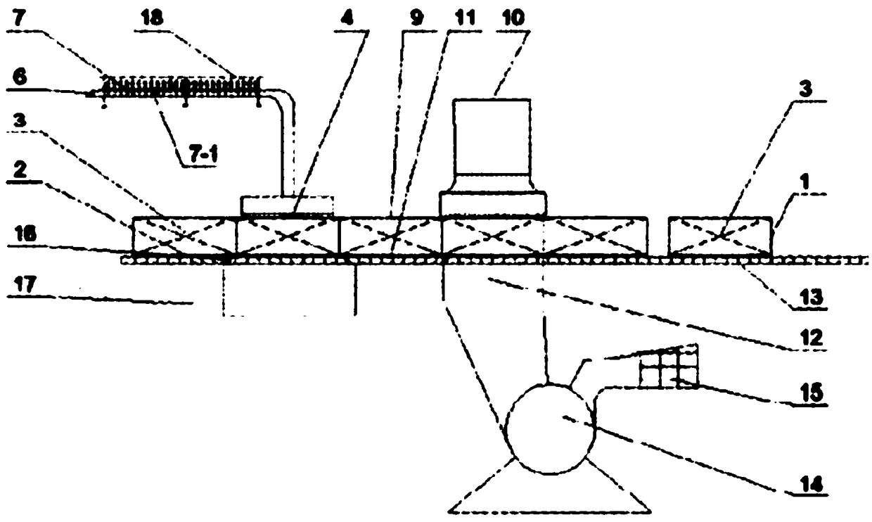
[0023] Embodiment three: as image 3 As shown, the shown single cooling tower heat storage device is composed of a housing 1, a support device 2, and a heat storage body 3. The support device 2 is fixed on the lower part of the housing 1, and there is a heat storage body 3 on the support device in the housing. The latter is always a fixed thermal storage device, and the circulating water is switched between multiple cooling towers under the control of the valve 5; during operation, the valve 5 corresponding to the cooling towers of the A group on the circulating water pipeline 6 is opened, and the circulation The water comes from the distributor 4 at the end of the circulating water pipe, and the water is evenly distributed on the heat storage body 3. The circulating water flows down from the distributor 4, and enters the heat storage body 3 from the inlet 9 of the heat storage body device. The heat body 3 is fully contacted, the circulating water transfers its heat to the the...
PUM
 Abstract
Description
Claims
Application Information
 - R&D Engineer
- R&D Manager
- IP Professional
- Industry Leading Data Capabilities
- Powerful AI technology
- Patent DNA Extraction
Browse by: Latest US Patents, China's latest patents, Technical Efficacy Thesaurus, Application Domain, Technology Topic, Popular Technical Reports.
© 2024 PatSnap. All rights reserved.Legal|Privacy policy|Modern Slavery Act Transparency Statement|Sitemap|About US| Contact US: help@patsnap.com