Heat exchanger and heat exchanger system
A heat exchanger and thermal conductivity technology, applied in indirect heat exchangers, heat exchanger types, heat sinks, etc., can solve the problems of long liquefaction time and large loss of cooling capacity, so as to increase the cooling capacity and improve the heat transfer capacity. Thermal efficiency, the effect of increasing the heat exchange area
- Summary
- Abstract
- Description
- Claims
- Application Information
AI Technical Summary
Problems solved by technology
Method used
Image

Examples
Embodiment 1
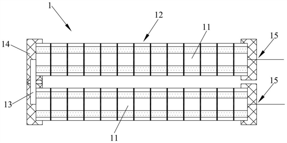
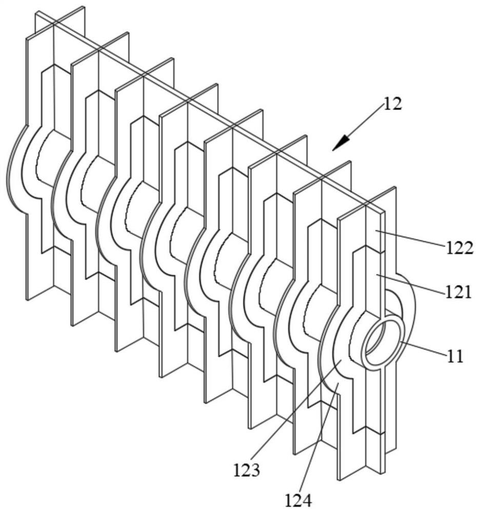
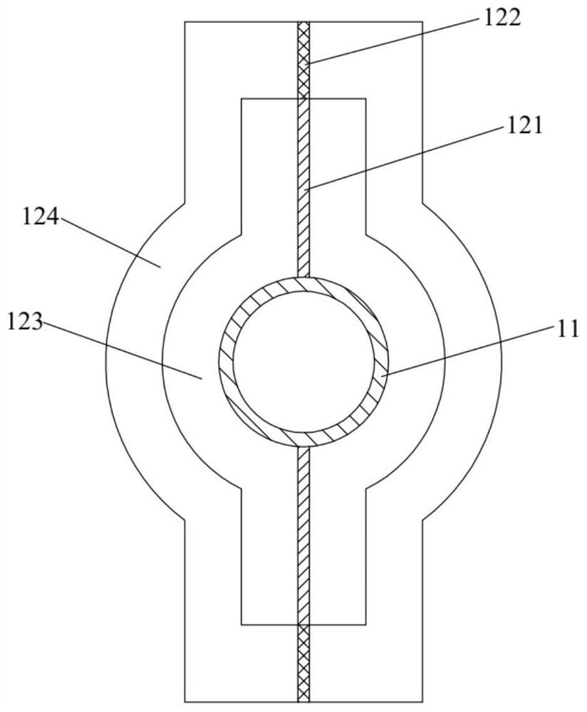
[0044] Such as Figure 1-Figure 3 As shown, this embodiment provides a heat exchanger. The heat exchanger 1 includes a heat exchange assembly, and the heat exchange assembly includes a row tube 11 and fins 12. The row tube 11 can be filled with brine or heat carrier. The fins 12 are arranged on the outer wall of the row tube 11 , and the height of the fin 12 extends along the radial direction of the row tube 11 . The fins 12 include first fins and second fins, the plate surface of the first fin is parallel to the axis of the row pipe 11, which is equivalent to the longitudinal fin of the first fin position, and the plate surface of the second fin is parallel to the axis of the row pipe The axis of 11 is vertical, which is equivalent to that the second fin is a transverse fin. The first fin includes a first heat conduction part 121 and a second heat conduction part 122 sequentially connected to the row pipe 11 , and the thermal conductivity of the second heat transfer part 122...
Embodiment 2
[0066] Such as Figure 4 As shown, this embodiment provides a heat exchanger system, including the heat exchanger 1 provided in Embodiment 1, and also includes a switching valve 5, a low-temperature cold source and a high-temperature heat source 6, and the low-temperature cold source and high-temperature heat source 6 pass through the switching valve 5 It communicates with the row pipe 11 to feed brine or heat transfer agent into the row pipe 11. Specifically, in this embodiment, the switching valve 5 is a four-way valve. In the de-icing working condition, the low-temperature cooling source is communicated with the exhaust pipe 11 by switching the switching valve 5, so as to pass the brine into the exhaust pipe 11; in the deicing working condition, by switching the switching valve 5, the The high-temperature heat source communicates with the row pipe 11 to feed heat carrier into the row pipe 11 .
Embodiment 3
[0068] Such as Figure 5 As shown, this embodiment provides a heat exchanger system, including the heat exchanger 1 provided in Embodiment 1, and also includes a cold storage tank 2, a filter screen 3, a circulation assembly 4, a switching valve 5, and a low-temperature cold source and a high-temperature heat source 6 . Water and ice are housed in the cold storage tank 2 . The filter screen 3 is installed on the top of the cold storage tank 2 and immersed in water. The circulation assembly 4 comprises a circulation pipeline 41, a valve 42, a water pump 43 and a water distributor nozzle 44. The inlet 411 of the circulation pipeline 41 is inserted in the water of the cold storage tank 2, and the inlet 411 is positioned above the filter screen 3. The valve 42 and The water pumps 43 are installed on the circulation pipeline 41 , and the outlet 412 of the circulation pipeline 41 communicates with the water distributor nozzle 44 , and the water distributor nozzle 44 is arranged at...
PUM
| Property | Measurement | Unit |
|---|---|---|
| thermal conductivity | aaaaa | aaaaa |
| thermal conductivity | aaaaa | aaaaa |
Abstract
Description
Claims
Application Information
 - R&D
- Intellectual Property
- Life Sciences
- Materials
- Tech Scout
- Unparalleled Data Quality
- Higher Quality Content
- 60% Fewer Hallucinations
Browse by: Latest US Patents, China's latest patents, Technical Efficacy Thesaurus, Application Domain, Technology Topic, Popular Technical Reports.
© 2025 PatSnap. All rights reserved.Legal|Privacy policy|Modern Slavery Act Transparency Statement|Sitemap|About US| Contact US: help@patsnap.com