Micro lubrication device

A technology of micro-lubrication and flowmeter, which is applied in the direction of metal processing machinery parts, maintenance and safety accessories, metal processing equipment, etc., can solve the problems of processing efficiency influence, variable diameter, multiple direction changes, lubricant delivery obstacles, etc., to meet the requirements of Efficient machining, low maintenance cost, and long operating life

Pending Publication Date: 2018-09-21
北京培峰技术有限责任公司
View PDF0 Cites 2 Cited by
  • Summary
  • Abstract
  • Description
  • Claims
  • Application Information

AI Technical Summary

Problems solved by technology

[0004] However, the micro-lubrication device in the prior art cannot meet the requirements in the ultra-deep hole processing occasions, and there are the following problems: 1) A small amount of lubricating oil is supplied by compressed air, and oil mist is formed at the end of the tool, which is not easy to be transported over a long distance , leading to poor lubrication effect at the cutting position of the tool; 2) In addition to the pipe, the delivery pipeline also includes the inner cavity of the main shaft, the inner cooling hole of the tool, and the channels of other mechanical parts. Guarantee; 3) Machine tool spindles, tools and accessories are all rotating parts. In high-efficiency machining, the spindle speed is very high, and the centrifugal force of high-speed rotation will hinder the delivery of lubricants, affecting the cutting effect, and the processing of small holes and deep holes 4) The amount of oil supplied by the micro-lubrication system is small, and there will be a time delay between the instructions given by the control system of the machine tool and the arrival of the lubricant in the cutting area, which will affect the processing efficiency

Method used


Image

  • Micro lubrication device
  • Micro lubrication device

Examples


Embodiment Construction

[0022] The present invention will be further explained below in conjunction with the drawings and embodiments. In the following detailed description, only certain exemplary embodiments of the present invention are described by way of illustration. Needless to say, those of ordinary skill in the art can realize that the described embodiments can be modified in various ways without departing from the spirit and scope of the present invention. Therefore, the drawings and description are illustrative in nature, and are not used to limit the protection scope of the claims.

[0023] In addition, the technical features involved in the various embodiments of the present invention described below can be combined with each other as long as they do not conflict with each other.

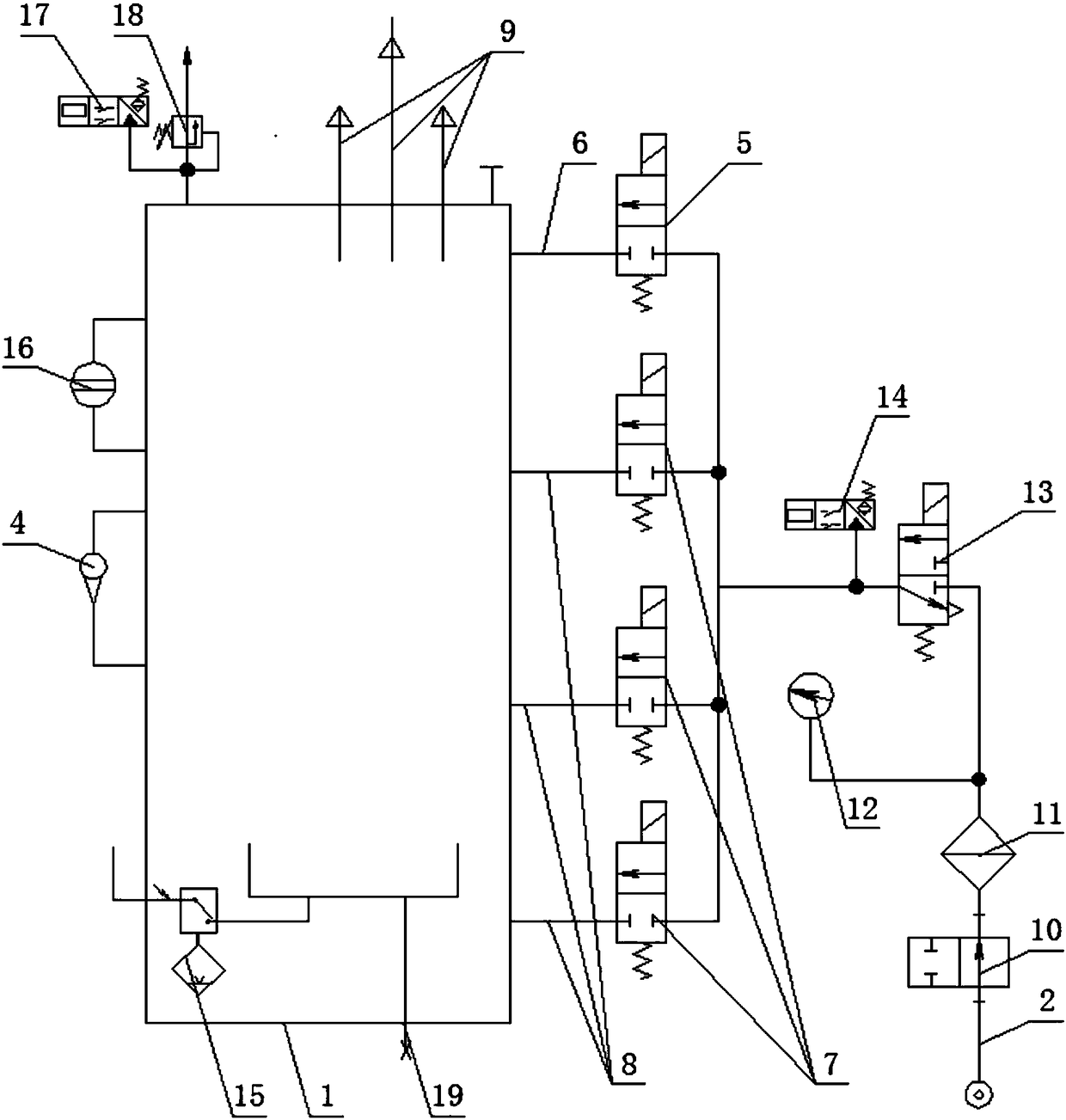
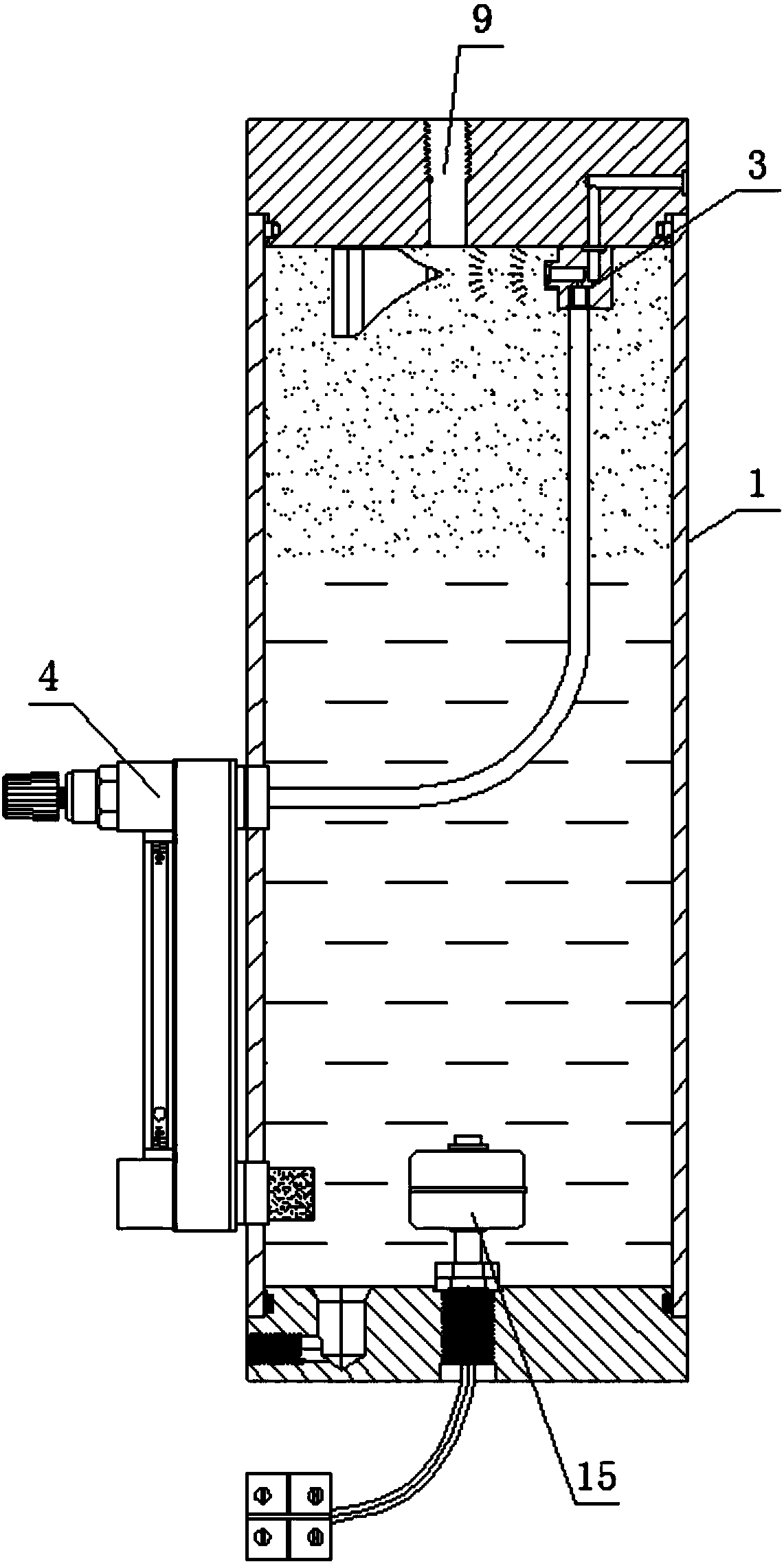
[0024] Such as figure 1 with figure 2 As shown, a micro-lubrication device includes an oil storage tank 1 and an air source inlet pipe 2 connected to a compressed air source. The air source inlet pipe 2 is connect...


PUM


Abstract

The invention discloses a micro lubrication device. The micro lubrication device comprises an oil storage tank and an air source inlet pipe, wherein the air source inlet pipe is connected with an aerosol generation control valve set; the aerosol generation control valve set is connected with an aerosol generator; a liquid inlet end of the aerosol generator is connected with a flow gauge; the air source inlet pipe is also connected with an aerosol mixing and air replenishing valve; the aerosol mixing and air replenishing valve is connected with an aerosol output pressure air pipe extending to the upper part of the oil storage tank; the top of the oil storage tank is connected with an aerosol outlet set. The micro lubrication device is capable of generating aerosol in a pressure container, outputting and controlling the generation amount of the aerosol; the aerosol is used for replacing the conventional cutting fluid for processing metals, so that the metal cutting positions are efficiently, greenly and environmentally friendly lubricated and cooled; the aerosol is especially applied to places for processing deep holes with length-diameter ratio being greater than 30-70, and cuttingand processing cutters with ultra-small inner holes, cutters with large inner cooling holes and cutters with multiple inner cooling holes; meanwhile, the aerosol can be controlled so as to meet different requirements of cutting and processing of various types of metals on lubrication.

Description

Technical field [0001] The invention relates to a micro-lubrication device of a micro-lubrication device. Background technique [0002] The machining field needs to use a large amount of cutting fluid, which has become an important pollution to the environment in the machining field, and has caused various negative effects. The waste cutting fluid is an important source of soil and air pollution, and the cutting fluid (emulsion) volatilizes. Oil mist is an important cause of skin diseases of operators. It is easy to cause various respiratory diseases after being inhaled by workers. At the same time, the thermal shock effect of cutting fluid (emulsion) on the surface of the tool may cause microcracks, which is an important factor affecting tool life. It also forms a limiting factor for the further improvement of machining efficiency. The fine metal chips present in the cutting fluid (emulsion) circulation system pose a threat to the quality of metal processing. [0003] The micro-l...

Claims


Application Information

Patent Timeline
IPC IPC(8): B23Q11/10
CPCB23Q11/1015B23Q11/1046B23Q11/1061
Inventor 樊震宇李松联
Owner 北京培峰技术有限责任公司
Why Eureka
Try Eureka