Method for growing crystal optical fiber core in crystal cladding layer

A crystal fiber and crystal growth technology, applied in the directions of crystal growth, single crystal growth, single crystal growth, etc., can solve the problems of easy cracking of cladding, low sol-gel efficiency, and undesired crystal cladding, and achieve consistent thermal expansion coefficients , good laser beam quality, avoid the effect of thermal stress

Active Publication Date: 2018-08-28
TONGJI UNIV
View PDF4 Cites 5 Cited by
  • Summary
  • Abstract
  • Description
  • Claims
  • Application Information

AI Technical Summary

Problems solved by technology

[0003] However, almost all optical fibers need cladding, not only to confine the beam inside the fiber, but also to isolate the fiber from the surrounding environment to maintain the integrity of the fiber. The cladding can also be used to increase the strength of the fiber. For Silica optical fiber, the cladding of the optical fiber is made by putting the quartz tube and the quartz core together to make a prefabricated rod, which is co-drawn in the fiber drawing tower, because the quartz is heated to soften and has a state between solid and liquid. The softened state exists, the dopant that has been doped into the core will not diffuse, and the refractive index distribution in the original preform will be maintained. For the crystal fiber, since the crystal is in a liquid state after melting, it can diffuse freely, so the dopant in the core rod It is possible for the ions to diffuse into the tube rod, and the tube rod as the fiber cladding does not allow the presence of doping ions, so it is not advisable to make the crystal cladding by the method of making the quartz cladding
Units at home and abroad are trying sol-gel to make crystal optical fiber cladding, but no substantial progress has been made, because the efficiency of sol-gel is too low, and the cladding with a thickness of 5 μm can only be obtained after 10 sol-gel operations, which is far from the final The usable thickness of 200-300μm is far away, and the cladding made by sol-gel is easy to crack
At present, there is no mature process report on crystal fiber with crystal cladding at home and abroad. It is reported that the crystal core and quartz cladding are used. Good beam quality, but it does not have much effect on the amplification of laser power. The US ArmyResearch Laboratory and ONYX Optics turned to study planar guided waves---that is, the cross-section of the core rod and cladding was made square, and the core and cladding They are tightly bonded by thermal bonding, and the all-crystal fiber is truly achieved, but the qualification rate of this thermal bonding process is not high.

Method used


Image

  • Method for growing crystal optical fiber core in crystal cladding layer

Examples


Embodiment 1

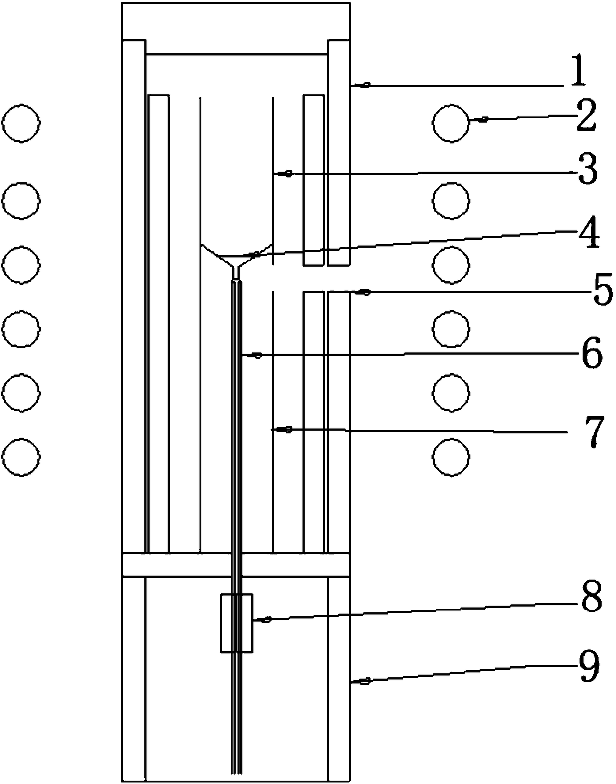
[0020] An all-crystal fiber and cladding manufacturing process adopts such as figure 1 The shown micro-drawing furnace device includes an insulation layer 1 arranged on the side wall of the furnace body, an induction coil 2 arranged outside the insulation layer 1, a quartz support column 9 arranged at the bottom of the furnace body, and a heater 3 is arranged above the quartz support column 9, There is a seed rod 8 inside, the transistor is installed on the seed rod 8 and passes through the heater 3, and an observation window 5 is set at the same height position of the rear heater 7 and the insulation layer 1.

[0021] The specific steps for making all-crystal fiber and cladding by using the above-mentioned device are as follows:

[0022] (1) Adopt the microporous crystal growth method to obtain the pure YAG microporous crystal 6 of length 40-160mm, the microporous crystal inner diameter is less than or equal to 1mm, or punch holes in the pure YAG crystal rod center to obtain ...

Embodiment 2

[0029] An all-crystal fiber and cladding manufacturing process adopts such as figure 1 The shown micro-drawing furnace device includes an insulation layer 1 arranged on the side wall of the furnace body, an induction coil 2 arranged outside the insulation layer 1, a quartz support column 9 arranged at the bottom of the furnace body, and a heater 3 is arranged above the quartz support column 9, There is a seed rod 8 inside, the transistor is installed on the seed rod 8 and passes through the heater 3, and an observation window 5 is set at the same height position of the rear heater 7 and the insulation layer 1.

[0030] The specific steps for making all-crystal fiber and cladding by using the above-mentioned device are as follows:

[0031] (1) Use the microporous crystal growth method to obtain pure YAG microporous crystals with a length of 40-160mm, and the inner diameter of the microporous crystals is less than or equal to 1mm, or punch holes in the center of the pure YAG cry...


PUM

PropertyMeasurementUnit
Lengthaaaaaaaaaa

Abstract

The invention relates to a method for growing a crystal optical fiber core in a crystal cladding layer. The method comprises the following steps: (1) obtaining a microporous crystal with a length of 40 to 160 mm by adopting a microporous crystal growing method, wherein the inner diameter of the microporous crystal is less than or equal to 1 mm, or obtaining the microporous crystal provided with micropores by perforating the center of a crystal rod with a machining method; (2) mounting the microporous crystal obtained in the step (1) on a micro pull-down furnace seed rod; (3) putting 1 to 2 g of a raw material into a crucible; (4) heating and melting the raw material in the crucible; (5) lifting up the seed rod to enable the microporous crystal to be in contact with a small hole in the bottom of the crucible, and allowing a melt in the crucible to enter the holes of the microporous crystal under the action of the gravity and the capillary action; (6) controlling the temperature of a post-heater to be reduced to room temperature at a cooling rate of 100 to 300 DEG C / h, so as to complete the whole crystal growing process. Compared with the prior art, the method has the advantages thata crystal core and the crystal cladding layer are seamlessly connected to obtain uniform refractive index distribution, so that a high-power crystal optical fiber laser device can be obtained.

Description

technical field [0001] The invention belongs to the technical field of crystal material preparation, and relates to a manufacturing process of high-power fiber laser optical fiber and cladding. Background technique [0002] Silica fiber has made outstanding contributions in optical communication, and some people want to use it as a high-power laser to solve the problem of thermal effect faced by current high-power lasers. Thermal effect will lead to problems such as thermal depolarization and thermal-induced diffraction loss, which seriously affect the laser. The main performance indicators such as output power, conversion efficiency, and beam quality, and even damage to the gain medium in severe cases, are the most important limiting factors for the performance of high-power lasers. In order to alleviate the impact of thermal effects, technicians in related fields use gain media in the form of slabs, DISKs, and optical fibers to increase the surface area to volume ratio of ...

Claims


Application Information

Patent Timeline
IPC IPC(8): C30B29/28C30B15/08H01S3/067
CPCC30B15/08C30B29/28H01S3/06716
Inventor 王东海徐军李纳薛艳艳罗平王庆国唐慧丽吴锋
Owner TONGJI UNIV
Why Eureka
Try Eureka