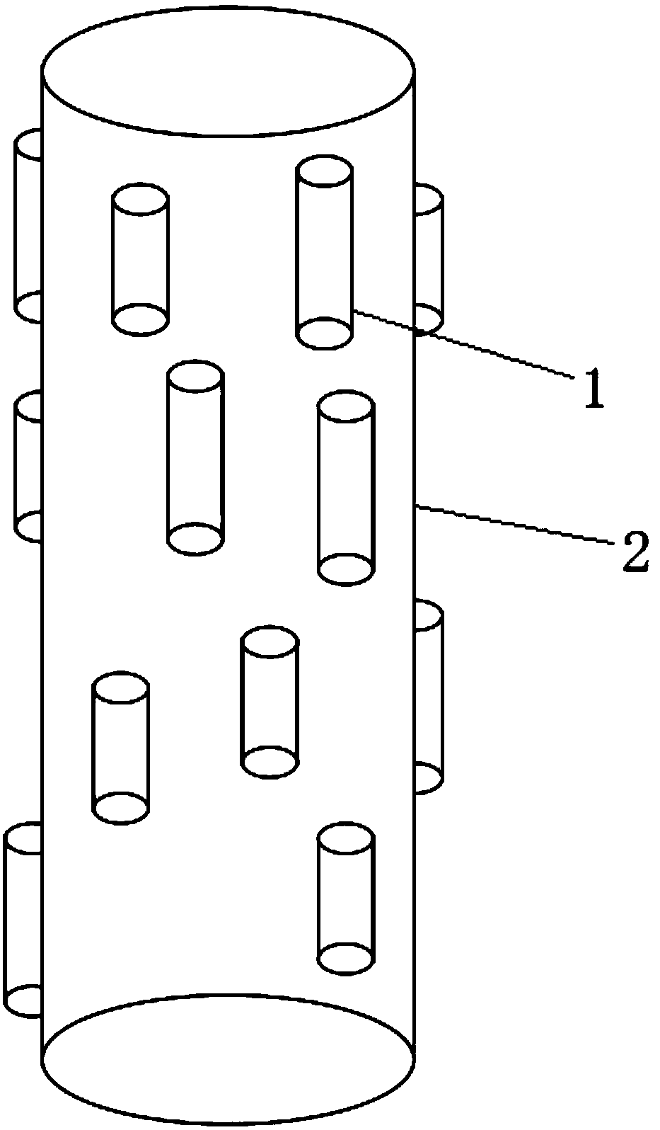
A kind of preparation method of piezoelectric photocatalytic composite fiber
A composite fiber and photocatalytic technology, which is applied in the field of ceramic nanofibers, can solve the problems of reducing photocatalytic reaction efficiency and less interface exposure, and achieve the effect of improving photocatalytic reaction efficiency, improving mechanical properties, and broad application prospects
- Summary
- Abstract
- Description
- Claims
- Application Information
AI Technical Summary
Problems solved by technology
Method used
Image
Examples
preparation example Construction
[0038] A kind of preparation method of piezoelectric photocatalytic composite fiber of the present invention, specifically implement according to the following steps:
[0039] Step 1. Prepare raw materials;
[0040] Prepare photocatalytic nanofibers, spinnable polymer A, solvent A, piezoelectric ceramic precursor, spinnable polymer B and solvent B;
[0041]Photocatalytic nanofibers as TiO 2 Nanofibers, ZnO nanofibers, SnO 2 nanofibers or CdS nanofibers;
[0042] The diameter of the photocatalytic nanofiber is 80nm-150nm, and the aspect ratio of the photocatalytic nanofiber is 5-20.
[0043] Step 2, preparing spinning solution;
[0044] Firstly, the spinnable polymer A is added to the solvent A, and mixed uniformly to obtain a polymer solution, and then photocatalytic nanofibers are added to the polymer solution to prepare a casing spinning solution;
[0045] The material composition of the shell spinning solution in terms of mass percentage is: 10%-25% of photocatalytic n...
Embodiment 1
[0065] Preparation of BaTiO 3 -TiO 2 Piezoelectric photocatalytic composite fiber
[0066] Firstly, TiO with a diameter of 80nm and an aspect ratio of 10 was taken. 2 nanofibers; then completely dissolve 1gPVP (polyvinylpyrrolidone) in 10mL absolute ethanol, and add 1.1gTiO 2 After nanofibers, the shell spinning solution was prepared; 1.215g PVP was completely dissolved in a mixed solution consisting of 4mL acetic acid and 6mL absolute ethanol, and 1.672g barium acetate and 1.861g isopropyl titanate were added to make the inner core spinning solution liquid;
[0067] Then put the obtained shell spinning solution and inner core spinning solution into the propulsion pump, adjust the spinning voltage to 20kv, the receiving distance is 18cm, the spinning temperature is 20°C, the humidity is 10%, and the casing spinning solution advances the speed 0.3mL / h, the propulsion speed of the inner core spinning solution is 0.15mL / h, and coaxial electrospinning is carried out to obtain ...
Embodiment 2
[0071] Preparation of BiFeO 3 -ZnO piezoelectric photocatalytic composite fiber
[0072] First get the ZnO nanofibers with a diameter of 90nm and an aspect ratio of 20; then completely dissolve 3.436gPS (polystyrene) in 10mLDMF, and add 4.295gZnO nanofibers to obtain a shell spinning solution; completely dissolve 1.050gPVP in In the mixed solution that is made up of 3mL ethylene glycol methyl ether, 5mLDMF and 2mL acetone, and add 1.789g bismuth nitrate and 1.099g ferric nitrate to make inner core spinning solution;
[0073] Then put the obtained shell spinning solution and inner core spinning solution into the propulsion pump, adjust the spinning voltage to 24kv, the receiving distance is 20cm, the spinning temperature is 25°C, the humidity is 20%, and the shell spinning solution advances the speed 0.2mL / h, the propulsion speed of the inner core spinning solution is 0.2mL / h, and coaxial electrospinning is carried out to obtain the precursor composite fiber;
[0074] Afterwa...
PUM
| Property | Measurement | Unit |
|---|---|---|
| diameter | aaaaa | aaaaa |
| aspect ratio | aaaaa | aaaaa |
Abstract
Description
Claims
Application Information
 - R&D
- Intellectual Property
- Life Sciences
- Materials
- Tech Scout
- Unparalleled Data Quality
- Higher Quality Content
- 60% Fewer Hallucinations
Browse by: Latest US Patents, China's latest patents, Technical Efficacy Thesaurus, Application Domain, Technology Topic, Popular Technical Reports.
© 2025 PatSnap. All rights reserved.Legal|Privacy policy|Modern Slavery Act Transparency Statement|Sitemap|About US| Contact US: help@patsnap.com


