Nitrogen flow jetting type hard cutting machining device and cutting method

A hard cutting and processing device technology, applied in metal processing equipment, metal processing machinery parts, manufacturing tools, etc., can solve problems such as unsatisfactory use requirements, superhard tool chipping, etc., to increase service life and improve fatigue resistance The effect of intensity

Inactive Publication Date: 2018-08-14
GUANGZHOU UNIVERSITY
View PDF10 Cites 9 Cited by
  • Summary
  • Abstract
  • Description
  • Claims
  • Application Information

AI Technical Summary

Problems solved by technology

However, the dry ice used in this patent cools the processing area, so that the nitrogen-rich layer on the surface cannot be produced during the processing of the workpiece, which further improves the fatigue resistance of the workpiece surface
[0004] In addition, liquid nitrogen is used as a cooling medium to spray the surface for cutting, but it is easy to cause superhard tools to break, which cannot meet the requirements of use.

Method used


Image

  • Nitrogen flow jetting type hard cutting machining device and cutting method
  • Nitrogen flow jetting type hard cutting machining device and cutting method
  • Nitrogen flow jetting type hard cutting machining device and cutting method

Examples


Embodiment 1

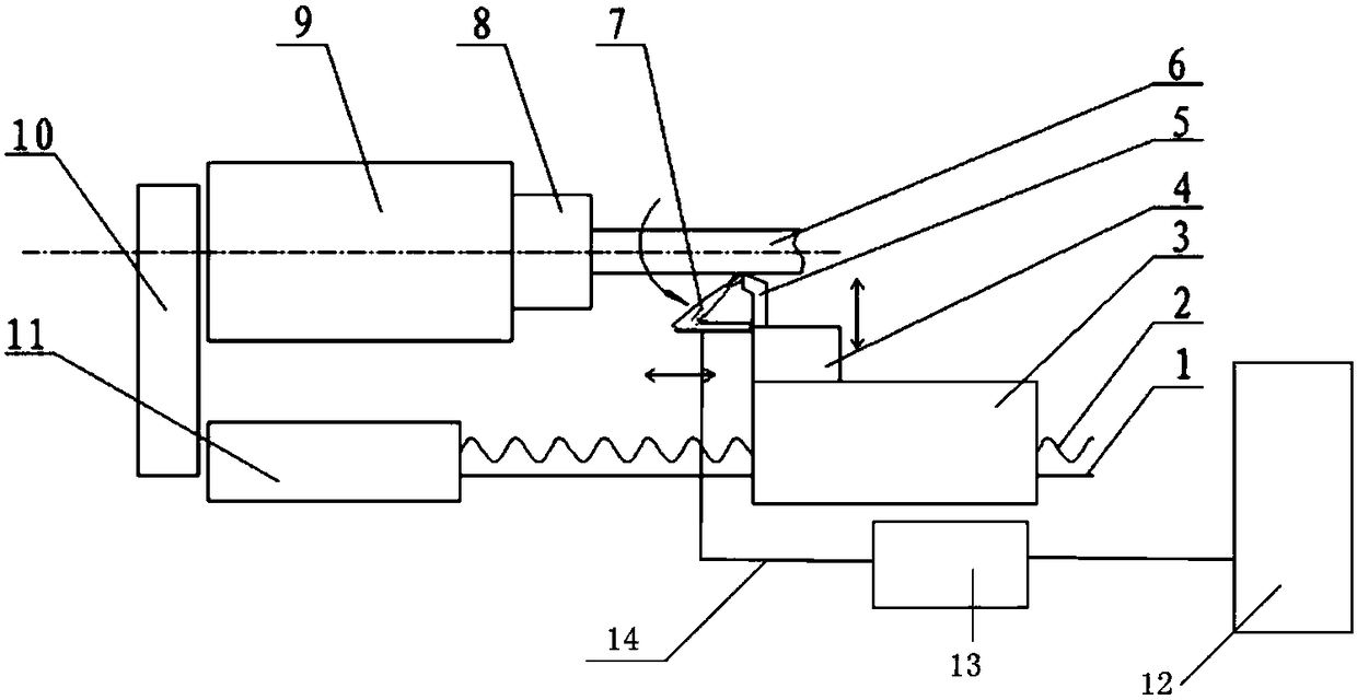
[0028] Such as Figure 1-4 As shown, this embodiment provides a nitrogen jet hard cutting device, including a cutting machine tool, and also includes a nitrogen jet device used in conjunction with the cutting machine tool, wherein,

[0029] The cutting machine tool includes an exchange gear box 10, a headstock 9 and a feed box 11 arranged in parallel, and the headstock 9 and the feed box 11 are respectively connected with the transmission of the exchange gear box 10. The other end is provided with a chuck 8 for clamping and fixing the hardened workpiece 6 to be cut and processed. During the machining process, the chuck 8 drives the hardened workpiece 6 to rotate during the rotation of the main shaft inside the headstock 9 ;

[0030] The other end of the feed box 11 is horizontally provided with a polished rod 1 and a screw mandrel 2, and also includes a sliding crate 3 capable of linear translation along the polished rod 1 driven by the screw rod 2, the sliding crate 3 is pro...

Embodiment 2

[0038] This embodiment provides a nitrogen jet hard cutting method, in which the superhard tool 5 is used to cut the hardened workpiece 6, and at the same time, the normal temperature nitrogen separated from the air by the nitrogen generator 12 is controlled by the nitrogen control system 13 The high-pressure nitrogen nozzle of the nitrogen jetting device is sprayed onto the processed surface of the hardened workpiece 6 at high speed, and nitrogen is used to cool down the superhard tool 5 and the hardened workpiece 6 while cutting, and to isolate the air for anti-oxidation treatment.

[0039] The present invention uses the normal-temperature safe and clean nitrogen separated from the air by the hollow nitrogen generator 12 as the cooling medium, so that the cutting fluid is not used in the cutting process, and the water can play the role of cleaning, lubricating and cooling, and it not only avoids cutting fluid It pollutes the environment and avoids the cracking of the superhar...


PUM


Abstract

The invention relates to the technical field of hard cutting machining, in particular to a nitrogen flow jetting type hard cutting machining device. According to the device and the method, a superhardcutter is adopted to perform cutting machining on a quenched workpiece, in the machining process, normal-temperature nitrogen separated by a nitrogen making machine from air passes from a nitrogen controller to a high-pressure nitrogen jet head to be jetted to the machining surface of the quenched workpiece at a high speed, on one hand, functions of strong-gas cleaning, lubricating and proper cooling are achieved through the gas medium, on the other hand, the nitrogen is used for isolating and protecting the surface of the workpiece against being oxidized, the machining surface is promoted toundergo friction chemical reaction with the nitrogen, a nitrogen-enriched layer which is beneficial to enhancing the surface quality is generated on the surface of the workpiece, and the method is awater-saving, material-saving and energy-saving green machining novel method without a cutting fluid required, with rough grinding replaced by lathe turning for machining the quenched workpiece.

Description

technical field [0001] The invention relates to the technical field of hard cutting, in particular to a nitrogen jet hard cutting device and a cutting method. Background technique [0002] Cutting can be divided into wet cutting and dry cutting, in which wet cutting uses cutting fluid to reduce the surface temperature of the workpiece processing, eliminate chips, cool and lubricate the processing area of ​​the workpiece, this method can improve the surface processing quality of the workpiece, but the cutting fluid is mechanical Important pollutants produced during processing, the discharge of which will have an impact on human health and environmental sanitation. For this reason, Chinese Publication No. CN102977983A discloses a pollution-free green cutting fluid and its preparation process. The cutting fluid involved in the invention uses agricultural waste, does not require chemical additives, and is harmless to the environment and human health. However, this method cannot...

Claims


Application Information

Patent Timeline
Patent Type & Authority Applications(China)
IPC IPC(8): B23Q11/10
CPCB23Q11/1038
Inventor 刘晓初周文波梁忠伟萧金瑞周佳华陈宥丞
Owner GUANGZHOU UNIVERSITY
Why Eureka
Try Eureka