A flexible locking positioning device and positioning method for blade air film hole processing

A technology of locking positioning and air film holes, which is applied in positioning devices, clamping devices, metal processing equipment, etc. and other problems, to achieve the effect of reliable locking and positioning, simple clamping and easy operation

Active Publication Date: 2020-04-17
AVIC BEIJING AERONAUTICAL MFG TECH RES INST
View PDF6 Cites 0 Cited by
  • Summary
  • Abstract
  • Description
  • Claims
  • Application Information

AI Technical Summary

Problems solved by technology

Tenon machining is done by broaching or milling based on the six-point datum of cast blade airfoil as the machining datum. The error caused by converting from the six-point datum of cast blade airfoil to the tenon datum is directly accumulated in the machining accuracy of air film hole, which is of great impact on air The hole position accuracy of the film hole has a great impact. Due to the certain error in the processing of the tenon, the positioning process of the blade tenon again directly affects the hole position accuracy of the air film hole, which in turn affects the cooling capacity of the turbine components.
At the same time, the deviation of the tenon air hole caused by casting defects makes the tenon processing of each blade correspondingly adjusted relative to the six-point benchmark, requiring the tooling to adjust the adjustment amount of the tenon of each blade, resulting in a large workload for tooling adjustment. The accuracy is difficult to guarantee, which has a great influence on the processing of air film holes

Method used


Image

  • A flexible locking positioning device and positioning method for blade air film hole processing
  • A flexible locking positioning device and positioning method for blade air film hole processing
  • A flexible locking positioning device and positioning method for blade air film hole processing

Examples


Embodiment 1

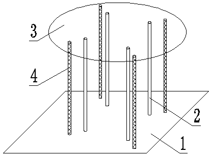
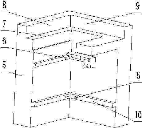
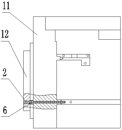
[0043] Such as Figure 1-3 As shown, a flexible locking and positioning device for machining blade air film holes includes a flexible locking structure and a positioning structure. The flexible locking structure includes a bridge 1 and a clamping seat 3 , the clamping seat 3 is provided with a tongue and groove, and the bridge 1 and the clamping seat 3 are floatingly and flexibly connected by jackscrews 2 and screws 4 . The positioning structure comprises a positioning wall 5, the upper part of the inner side wall of the positioning wall 5 is provided with a limiting portion, and the limiting portion is respectively provided with a first reference plane 7, a second reference plane 8 and a third reference plane 9, the inside of the positioning wall 5 Both the middle and the lower part of the wall are provided with convex parts 10, and the convex parts 10 are respectively provided with reference ball heads 6, the outer wall of the positioning wall 5 is provided with an end cover...

Embodiment 2

[0046] Such as Figure 1-3 As shown, a flexible locking and positioning device for machining blade air film holes includes a flexible locking structure and a positioning structure. The flexible locking structure includes a bridge 1 and a clamping seat 3 , the clamping seat 3 is provided with a tongue and groove, and the bridge 1 and the clamping seat 3 are floatingly and flexibly connected by four jacking screws 2 and four screws 4 . The positioning structure comprises a positioning wall 5, the upper part of the inner side wall of the positioning wall 5 is provided with a limiting portion, and the limiting portion is respectively provided with a first reference plane 7, a second reference plane 8 and a third reference plane 9, the inside of the positioning wall 5 The middle and lower parts of the wall are provided with convex parts 10, and six reference ball heads 6 are arranged on the convex parts 10. The outer wall of the positioning wall 5 is provided with an end cover 12, ...


PUM


Abstract

The invention provides a flexible locking and positioning method used for blade air film hole machining. According to the technical key points of the method, a flexible locking structure and a positioning structure are involved; the flexible locking structure comprises a slab bridge and a clamping base, mortises are formed in the clamping base, and the slab bridge and the clamping base are flexibly connected through jackscrews and screws; and the positioning structure comprises a positioning wall, a limit portion is arranged on the upper portion of the inner side wall of the positioning wall and provided with a first datum surface, a second datum surface and a third datum surface, protruding portions are arranged on the middle portion and the lower portion of the inner side wall of the positioning wall correspondingly, datum ball heads are arranged on the protruding portions correspondingly, an end cover is arranged on the outer side wall of the positioning wall, and a base is arrangedat the bottom of the positioning wall. According to the flexible locking and positioning method, through flexible connection of the flexible locking structure, flexible conversion from a six-point datum to a technological datum of a turbine blade body can be achieved, machining errors caused by blade tenon deviation are eliminated, blades are reliably locked and positioned, and clamping and operation are easy.

Description

technical field [0001] The invention relates to the technical field of special processing, in particular to a flexible locking device and a positioning method for processing blade air film holes. Background technique [0002] The turbine is the part with the largest thermal load and mechanical load in the aero-engine, and the working environment of the turbine blade is particularly harsh. In the engine cycle, it bears the impact of high-temperature and high-pressure gas after combustion, and the performance of the engine largely depends on the turbine inlet temperature. high and low. In order for these components to work safely and reliably even when the working environment temperature exceeds the melting point of the material, they need to be continuously cooled. Air film hole cooling technology can greatly improve engine performance, and at the same time put forward higher requirements for air film hole processing technology. [0003] With the development of aero-engines...

Claims


Application Information

Patent Timeline
Patent Type & Authority Patents(China)
IPC IPC(8): B23Q3/00
CPCB23Q3/00B23Q2703/10
Inventor 翟士民张明岐潘志福殷旻孙超
Owner AVIC BEIJING AERONAUTICAL MFG TECH RES INST
Why Eureka
Try Eureka