
Hot cathode-based gas discharge electron source

A gas discharge and electron source technology, which is applied in the thermionic cathode, electron emission electrode/cathode, traveling wave tube, etc., can solve the problem that the hot cathode of the space traveling wave tube cannot achieve fast startup, and the gas discharge hollow cathode has high working power and cannot be used. To meet the needs of small satellite systems and other issues, to achieve the effect of providing work efficiency, increasing cathode emission current, and ensuring stability

Active Publication Date: 2018-07-27
LANZHOU INST OF PHYSICS CHINESE ACADEMY OF SPACE TECH
View PDF5 Cites 2 Cited by
  • Summary
  • Abstract
  • Description
  • Claims
  • Application Information

AI Technical Summary

Problems solved by technology

The hot cathode of the space traveling wave tube needs to work in a confined space without any high-energy ion environment outside. The space traveling wave tube hot cathode requires a higher working vacuum degree, generally 10 -5 Pa, so the hot cathode of the space traveling wave tube cannot achieve fast startup, and the thermal efficiency of the cathode is low; while the gas discharge hollow cathode performs gas discharge in the hollow discharge cavity, and requires a high heating power during operation, and the maintenance discharge power is generally greater than 60W. Its stable emission current is generally greater than 1A, and its voltage oscillation value is relatively large in low current mode, generally greater than 10V, so the working power of the gas discharge hollow cathode is high and the emission current coverage is limited
[0004] It can be seen that none of the existing electronic source products can meet the needs of small satellite systems

Method used


Image

  • Hot cathode-based gas discharge electron source

Examples


Embodiment Construction

[0024] The present invention will be described in detail below with reference to the accompanying drawings and examples.

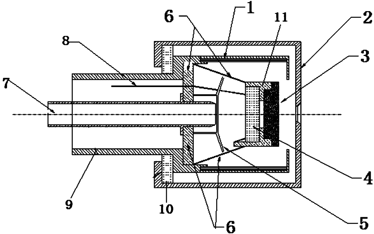
[0025] Such as figure 1 As shown, a gas discharge electron source based on a hot cathode provided in this embodiment includes: a heat shield part 1, an anode cover 2, an emitter 3, a hot wire part, a gas distribution baffle 5, a cathode support part 6, and a gas supply pipe Road 7, power supply positive input terminal 8 and heat shield support part 9;

[0026] Wherein, the heating wire component includes a heating wire 4 and a heating wire insulating ceramic 11, one end of the heating wire is connected to the positive input terminal 8 of the power supply, and the other end is connected to the cathode support member 6, and the cathode support member 6 is connected to the power supply ground. The heating wire is matched with the emitter 3 through the heating wire insulating ceramic 11, so that the heating wire 4 is opposite to the emitter 3 but not in conta...


PUM


Abstract

The invention provides a hot cathode-based gas discharge electron source, which can be quickly started, has low power required for the operation, and has a wide coverage range of emission current. Anemitter is directly heated by using a heating wire, a heat shielding component and an anode cover are additionally arranged outside a cathode, and the heat shielding component increases the thermal efficiency of the cathode and reduces the environmental requirements during the operation of the cathode; the anode cover can reduce the influence of external environment particle sputter etching on theemitter and prolong the service life of the emitter, and the anode cover also provides a discharge chamber for gas discharge, can absorb electrons in a discharge plasma and maintain the gas discharge, and can also restrain the directionality and size of the emitted electrons and improve the working efficiency of an electron source; and in addition, according to the scheme of the invention, a gassupply pipeline is arranged in the electron source for adding working medium gas to the gas discharge chamber, and by adding the working medium gas during the operation of the cathode, the emission current of the cathode can be effectively increased, and the coverage range of the emission current of the cathode can be extended.

Description

technical field [0001] The invention relates to the technical field of aerospace electric propulsion, in particular to a hot cathode-based gas discharge electron source for emitting small currents. Background technique [0002] Small satellites and microsatellites have triggered major changes in the aerospace field and the entire aerospace ecosystem. Due to their strong maneuverability and low cost, they have become international research hotspots. According to the latest report of the European consulting company, it is estimated that more than 3,600 small satellites will be launched in the next 10 years, which is a significant increase compared with the past 10 years. Small satellites and micro-satellites also put forward new requirements for the thrusters used by them. The power of the thrusters is on the order of tens of watts and hundreds of watts, and the electron source (cathode product) used in them is required to have a fast start. , Low working power (working power...

Claims


Application Information

Patent Timeline
Patent Type & Authority Applications(China)
IPC IPC(8): H01J19/04H01J19/14H01J25/34
CPCH01J19/04H01J19/14H01J25/34
Inventor 杨威郭宁张天平李娟唐福俊冯杰谷增杰
Owner LANZHOU INST OF PHYSICS CHINESE ACADEMY OF SPACE TECH
Learn More