
Ceramic bonding pad array shell

A pad array and ceramic technology, applied in the field of integrated circuit ceramic shells, can solve the problems of poor heat dissipation, affecting air convection, affecting the alignment of ball or column molds, etc., to achieve high mechanical reliability, improve heat dissipation capacity, Small size effect

Pending Publication Date: 2018-06-29
THE 13TH RES INST OF CHINA ELECTRONICS TECH GRP CORP
View PDF0 Cites 4 Cited by
  • Summary
  • Abstract
  • Description
  • Claims
  • Application Information

AI Technical Summary

Problems solved by technology

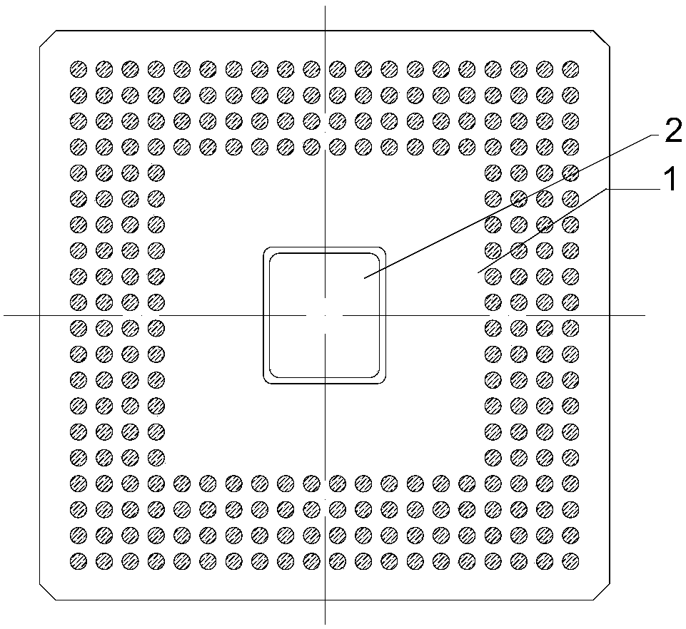
[0006] The purpose of the present invention is to provide a ceramic pad array housing to solve the technical problems that the ceramic pad array housing in the prior art affects the alignment of ball planting or column planting molds, and affects air convection and poor heat dissipation. It has no effect on the alignment of the ball planting or column planting mold, and can perform ball planting or column planting on the surface of the heat sink to improve the technical effect of heat dissipation

Method used


Image

  • Ceramic bonding pad array shell
  • Ceramic bonding pad array shell
  • Ceramic bonding pad array shell

Examples


Embodiment Construction

[0022] In order to make the technical problems, technical solutions and beneficial effects to be solved by the present invention clearer, the present invention will be further described in detail below in conjunction with the accompanying drawings and embodiments. It should be understood that the specific embodiments described here are only used to explain the present invention, not to limit the present invention.

[0023] It should be noted that when an element is referred to as being “fixed” or “disposed on” another element, it may be directly on the other element or be indirectly on the other element. When an element is referred to as being "connected to" another element, it can be directly connected to the other element or indirectly connected to the other element.

[0024] It is to be understood that the terms "length", "width", "top", "bottom", "front", "rear", "left", "right", "vertical", "horizontal", "top" , "bottom", "inner", "outer" and other indicated orientations...


PUM

PropertyMeasurementUnit
Pitchaaaaaaaaaa

Abstract

The invention discloses a ceramic bonding pad array shell and belongs to the technical field of ceramic shells of integrated circuits. The ceramic bonding pad array shell comprises a ceramic substrateand a T-shaped heat sink, wherein a cavity with steps is formed in the middle of the ceramic substrate; the upper surface of the heat sink is used for mounting chips; the heat sink is in matched overlap connection with the cavity; and the lower surface of the heat sink is co-planar to the lower surface of a bonding pad arranged on the lower surface of the ceramic substrate. According to the ceramic bonding pad array shell disclosed by the invention, the technical problems existing in the prior art that alignment of ball placement or column placement molds is influenced by the ceramic bondingpad array shell, air convection is influenced and heat dissipation is bad can be solved. The technical effects that alignment of ball placement or column placement molds is not influenced, ball placement or column placement can be performed on the surface of the heat sink and the heat dissipation ability is improved can be achieved.

Description

technical field [0001] The invention belongs to the technical field of integrated circuit ceramic shells, and more specifically relates to a ceramic pad array shell. Background technique [0002] The ceramic shell is developed on the basis of multilayer ceramic technology and ceramic-metal sealing technology, and is an important support for integrated circuits. Its basic functions include: 1) realize the mechanical support for the chip; 2) realize the isolation between the chip and the external environment; 3) realize the electrical signal connection between the chip and the external circuit; 4) realize the heat dissipation path of the chip. [0003] The electronic component housing refers to the package of the component, and its main function is to provide electrical (optical) signal interconnection, mechanical protection, environmental protection, and heat dissipation. In the field of high reliability and high performance applications, the ceramic shell based on alumina c...

Claims


Application Information

Patent Timeline
IPC IPC(8): H01L23/15H01L23/367
CPCH01L23/15H01L23/3675
Inventor 张崤君郭志伟
Owner THE 13TH RES INST OF CHINA ELECTRONICS TECH GRP CORP
Learn More