
Conveying system of heart assistant device

A technology of delivery system and cardiac assistance, applied in the field of delivery system, can solve problems such as increased difficulty, difficult to adapt to patients, increased difficulty, etc., to achieve the effect of making up for applicability defects, improving the success rate of surgery, and expanding the scope of application

Pending Publication Date: 2018-06-19
NINGBO DIOCHANGE MEDICAL TECH CO LTD
View PDF8 Cites 2 Cited by
  • Summary
  • Abstract
  • Description
  • Claims
  • Application Information

AI Technical Summary

Problems solved by technology

The defects of this mechanism are: 1. After the heart assist device is implanted, it should be closely attached to the outer surface of the heart before it can play a role. Therefore, the shape (or size) of the heart assist device before it is inserted into the heart should be smaller than that of the heart. shape (or size) at end-diastole, or even end-systole; with this in mind, the operator places a cardiac assist device on a beating heart in a series of cuffs from the apex, across the outer surface of the ventricle, and down to the atrioventricular groove of the heart During the insertion process, as the deployment mechanism, especially the distal end of the deployment mechanism, and the inner surface of the cardiac assist device come into more contact with the outer surface of the heart, the frictional resistance becomes larger and the insertion becomes more and more difficult. The higher the value, the more difficult it is for the operator to manipulate the delivery system to implant the cardiac assist device
2. According to the theory of cardiac torsional motion, in addition to periodic systolic and diastolic motions, the heart also undergoes periodic reciprocating torsional motions in the direction of circular rotation during the process of systole and diastole. Difficulty in inserting, and it is also very likely to cause damage to the surface of the heart
3. The shape (or size) of each patient's heart is different, which makes the shape (or size) of the heart assist device also different, which requires that the heart assist device should have a certain directionality on the circumference, thus further increasing the operation Difficulty of one-time placement to the target location on the surface of the heart
This mechanism still has the same problems as Mardil’s CorCap: 1. The heart assist device slides to the surface of the heart between the inner guide and the outer guide. The guide needs to be positioned accurately, and it is not easy to adjust the position twice. Difficulty in placing the cardiac assist device at the target position on the surface of the heart; 2. The periodic reciprocating torsional movement in the direction of the heart's circular rotation also affects the positioning accuracy of the device; 3. The shape of the push rod in the delivery system has limitations, Difficult to accommodate all patients with different heart shapes (or sizes)

Method used


Image

  • Conveying system of heart assistant device
  • Conveying system of heart assistant device
  • Conveying system of heart assistant device

Examples


Embodiment 1

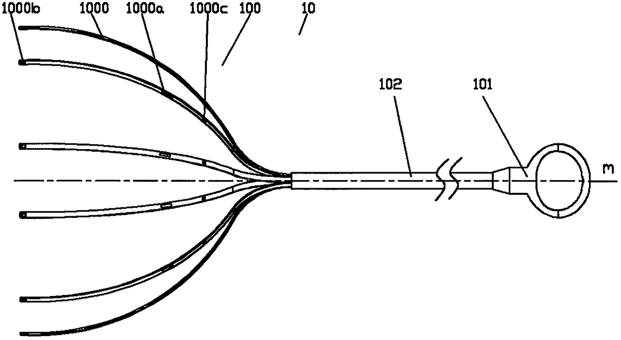
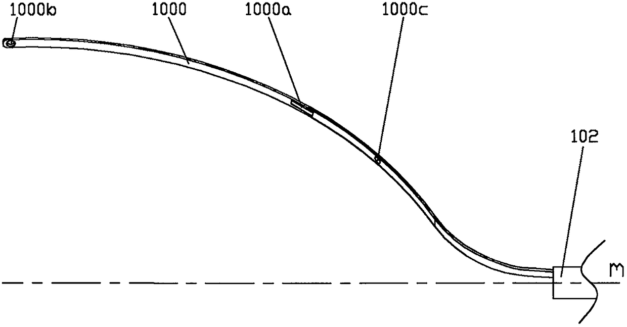
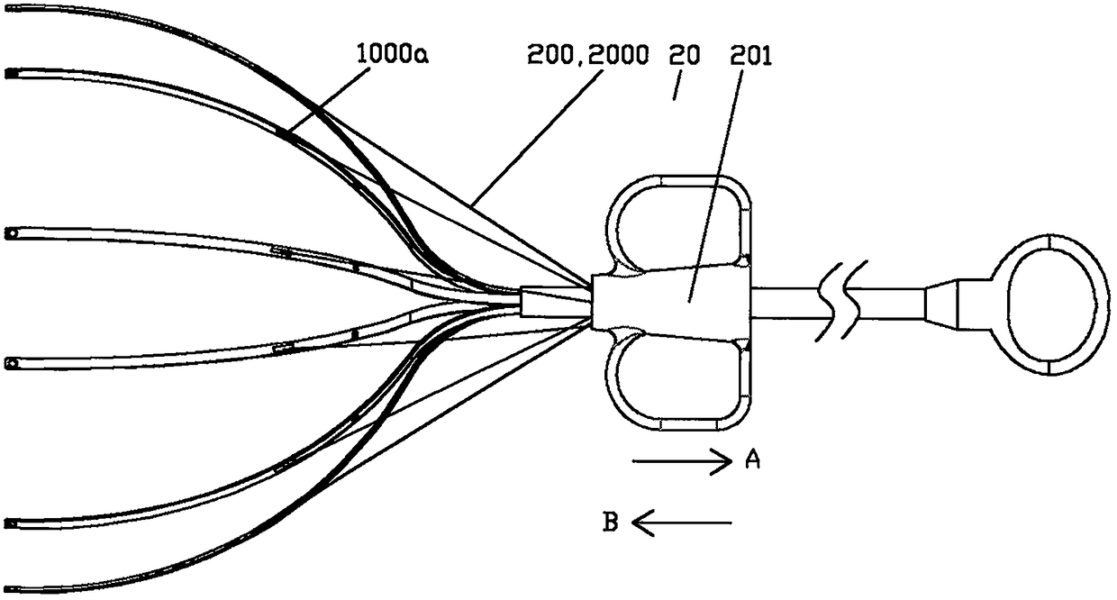
[0054] Such as Figure 1a As shown, the delivery system of the heart assist device provided by the present invention (hereinafter referred to as "the delivery system") includes a retractable assembly 10 and a traction assembly 20, and the retractable assembly 10 includes a retractable handle 101, which is located far from the retractable handle 101 The retractable strip assembly 100 at the end and the retractable connecting piece 102 for fixedly connecting the retractable handle 101 and the retractable strip assembly 100, the retractable strip assembly 100 is composed of multiple Arranged and composed of retractable strips 1000 divergent to the far end, the proximal end of the retractable strip assembly 100 is fixedly connected with the retractable connector 102; The traction handle 201, the retractable strip assembly 100 is connected with the traction connector 200, the traction handle 201 or the retractable handle 101 is operated, and the relative position of the two is chang...

Embodiment 2

[0063] Such as Figure 6 to Figure 11 As shown, based on the first embodiment, the difference between the second embodiment and the first embodiment is that the traction connector 200 includes a traction platen 202 arranged in the space surrounded by a plurality of retractable strips 1000, and the traction platen 202 is coaxial with the retractable connector 102, the traction pressure plate 202 is connected with the traction handle 201 through the traction connector 200, in this case, the traction pressure of the retractable strip assembly 100 and the traction connector 200 Disk 202 is connected. In one embodiment, the traction connector 200 is multiple traction wires 2000 , one end of the multiple traction wires 2000 is connected to the traction platen 202 , and the other end of the multiple traction wires 2000 is connected to the traction handle 201 . In one embodiment, the traction connector 200 is composed of one or more traction wires 2000 and a traction connection trans...

Embodiment 3

[0069] Such as Figure 12 As shown, based on the first embodiment, the first difference between the third embodiment and the first embodiment is that the delivery system also includes an implant release assembly, which consists of an implant release handle 301 and an implant release handle 301. The implant release wire 3000 is composed of an implant release handle 301 that can slide relative to the traction connector 200 or the retractable connector 102. There are one or more implant release wires 3000; in heart assist devices (that is: implant) in the unreleased state, the distal end of the implant release wire 3000 fits with the distal end of the retractable strip 1000, and further, in order to make the two fit better, the retractable The outside of the strip 1000 and the implant release wire 3000 cover the retractable strip sleeve 1001 at least in their distal regions. In addition, if Figure 1b and Figure 14 As shown, in one embodiment, the retractable bar 1000 can be ...


PUM


Abstract

The invention relates to a conveying system of a heart assistant device. The conveying system comprises a put-away assembly and a traction assembly; the put-away assembly comprises a put-away handle,a put-away strip assembly at the far end of the put-away handle, and a put-away connecting piece used for being fixedly connected with the put-away handle and the put-away strip assembly; the put-awaystrip assembly is composed of a plurality of put-away strips which are distributed circumferentially along the central axis of the put-away connecting piece, and the far ends of the put-away strips are dispersed. The traction assembly comprises a traction connecting piece and a traction handle connected with the near end of the traction connecting piece, the put-away strip assembly is connected with the traction connecting piece, the traction handle or the put-away handle is operated to change the relative position of the put-away strip assembly and the traction connecting piece, and the expansion or contraction amplitude adjustment of the put-away strip assembly is achieved. The conveying system is simple in structure, convenient to operate, easy to adjust in real time and adjust for thesecond time, high in adaptability, capable of reducing the implanting difficulty of the heart assistant device, and capable of reducing risks caused by misoperation in operations.

Description

technical field [0001] The invention belongs to the field of medical devices, in particular to a delivery system for delivering a heart assist device to the surface of the heart. Background technique [0002] In recent years, the prevalence of heart failure has been increasing year by year, becoming a serious public health problem. Patients with clinical symptoms are similar to malignant tumors. There are many etiologies, one of the most common being dilated cardiomyopathy. Dilated cardiomyopathy is characterized by a low ejection fraction of the heart, which makes it difficult to pump enough blood to meet the metabolic demands of the body's tissues, especially the demand for oxygen. Wrapping, or restraining, the heart has been shown to improve pumping efficiency in those affected by dilated cardiomyopathy. The heart assist device is suitable for patients to achieve the purpose of treating dilated cardiomyopathy by directly applying pressure to the left ventricle and reduc...

Claims


Application Information

Patent Timeline
IPC IPC(8): A61B17/00A61F2/24
CPCA61B17/00234A61F2/2481A61B2017/00243A61B2017/00238A61F2002/2484
Inventor 李彪丁宗光董娟
Owner NINGBO DIOCHANGE MEDICAL TECH CO LTD
Learn More