Method and device for representing and calibrating TSV electroplating additive parameters
A calibration method and characterization technology, applied in the field of electrochemistry, can solve problems such as the complexity of the action mechanism of additives and the difficulty of measuring various parameters
- Summary
- Abstract
- Description
- Claims
- Application Information
AI Technical Summary
Problems solved by technology
Method used
Image

Examples
Embodiment 1
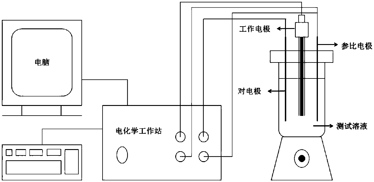
[0052] The exchange current density and cathodic transfer coefficient of the electroplating solution without TSV electroplating additives were measured by linear voltammetry. Linear sweep voltammetry measures the current at the working electrode, where the voltage between the working and reference electrodes varies linearly with time.
[0053] Exchange current density: When the electrode reaction is in equilibrium, the two directions of the electrode reaction proceed at the same speed, and the corresponding absolute value of the current density of the anodic reaction and the cathodic reaction in the two reaction directions is called the exchange current density.
[0054] Cathode transfer coefficient: It characterizes the increase degree of Gibbs free energy of activation of cathode reduction reaction.
[0055] Step One: Prepare the Test Solution
[0056] Measure 40 milliliters of SYS2510 electroplating solution with a beaker as a test solution;
[0057] Step 2: Electrode Pre...
Embodiment 2
[0073] Characterization and Calibration of Inhibitor Diffusion Coefficient in Electroplating Bath
[0074] Step One: Prepare the Test Solution
[0075] Measure 35ml of SYS2510 solution as the electroplating solution and place it in a beaker, use a syringe to take 5ml of the mixed solution, including 4.6ml of SYS2510 and 0.4ml of UPT3320S, as an additive;
[0076] Step 2: Electrode Pretreatment
[0077] Polish the electrode with sandpaper to remove the oxide layer on the surface of the electrode, and clean the polished electrode with deionized water to ensure good conductivity of the electrode;
[0078] Step 3: Inject the test solution into the plating tank and install the electrodes
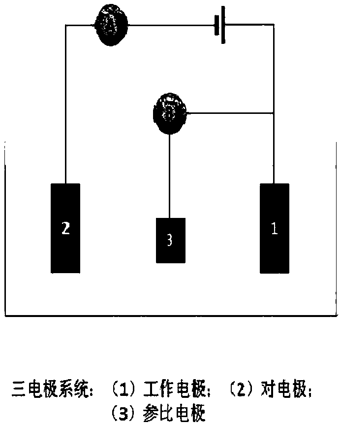
[0079] Inject the 35ml SYS2510 solution prepared in the beaker into the electroplating tank, follow the Figure 5 As shown, the counter electrode (platinum electrode), working electrode (platinum rotating disk electrode) and reference electrode (mercurous sulfate electrode) are installed on th...
Embodiment 3
[0090] Characterization and Calibration of Accelerator Diffusion Coefficient in Electroplating Bath
[0091] Step One: Prepare the Test Solution
[0092] Measure 4.875ml of SYS2510 and 34.125ml of deionized water, mix them as plating solution and place in a beaker, use a syringe to take 1ml of UPT3320A solution as an additive;
[0093] Step 2: Electrode Pretreatment
[0094] Polish the electrode with sandpaper to remove the oxide layer on the surface of the electrode, and clean the polished electrode with deionized water to ensure good conductivity of the electrode;
[0095] Step 3: Inject the test solution into the plating tank and install the electrodes
[0096] Inject 4.875 milliliters of SYS2510 and 34.125 milliliters of deionized water prepared in the beaker into the electroplating tank, and place the counter electrode (platinum electrode), working electrode (platinum rotating disk electrode) and reference electrode (saturated calomel electrode) as shown in Figure 5 El...
PUM
 Abstract
Description
Claims
Application Information
 - R&D
- Intellectual Property
- Life Sciences
- Materials
- Tech Scout
- Unparalleled Data Quality
- Higher Quality Content
- 60% Fewer Hallucinations
Browse by: Latest US Patents, China's latest patents, Technical Efficacy Thesaurus, Application Domain, Technology Topic, Popular Technical Reports.
© 2025 PatSnap. All rights reserved.Legal|Privacy policy|Modern Slavery Act Transparency Statement|Sitemap|About US| Contact US: help@patsnap.com