
Wireless integrated X ray flaw detector

An X-ray and flaw detector technology, which is used in material analysis using radiation, material analysis using wave/particle radiation, measuring devices, etc., can solve problems such as instability, laborious handling, interference, etc., to reduce weight and avoid attenuation. , the effect of poor stability

Pending Publication Date: 2018-05-18
丹东市祯晟科技有限公司
View PDF0 Cites 0 Cited by
  • Summary
  • Abstract
  • Description
  • Claims
  • Application Information

AI Technical Summary

Problems solved by technology

Portable industrial X-ray flaw detectors have the following problems: (1) There is a certain degree of voltage drop in the cable link between the controller and the generator, and the 10*1.5 cable 25 meters long will cause a voltage attenuation of 30V; (2) The controller to the generator The cable used for the cable link of the device is heavy and laborious to carry, and the distance that can be detected is limited by the cable; (3) 220V axial flow fan has an air volume of 220m per hour 3 Every hour, the portable industrial X-ray flaw detector needs to rest at 1::1, the work efficiency is low, the heat dissipation time is long, the heat dissipation effect is not good, and it is easy to burn out the X-ray tube; (4) The controller is large and cannot be adjusted Parameters; (5) The magnetic positioning of the single-chip microcomputer control system of the portable industrial X-ray flaw detector is susceptible to environmental interference. When encountering strong magnetism, such as mobile phone signals, it will interfere with it and be unstable.

Method used


Image

  • Wireless integrated X ray flaw detector
  • Wireless integrated X ray flaw detector
  • Wireless integrated X ray flaw detector

Examples


Embodiment Construction

[0047] In order to further understand the present invention, the preferred embodiments of the present invention are described below in conjunction with examples, but it should be understood that these descriptions are only to further illustrate the features and advantages of the present invention, rather than limiting the claims of the present invention.

[0048] The wireless integrated X-ray flaw detector of the present invention includes two parts: a controller and a generator. The controller is a PDA that uses a PLC control system to control the generator through a touch screen, and adjusts kilovolts, time, and milliamps through the touch screen, and has a built-in 24V battery; the controller displays: power supply voltage, generator pressure, generator temperature, and real-time exposure Time, exposure real-time voltage, exposure real-time mA, total device startup time, total device exposure time, total device exposure times, total device startup times, status (preparation,...


PUM

PropertyMeasurementUnit
Heightaaaaaaaaaa
Depthaaaaaaaaaa
Widthaaaaaaaaaa

Abstract

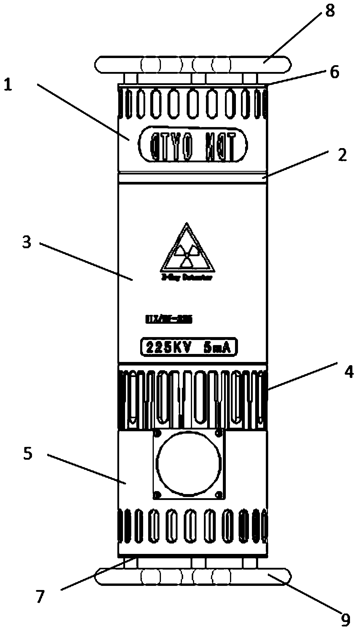
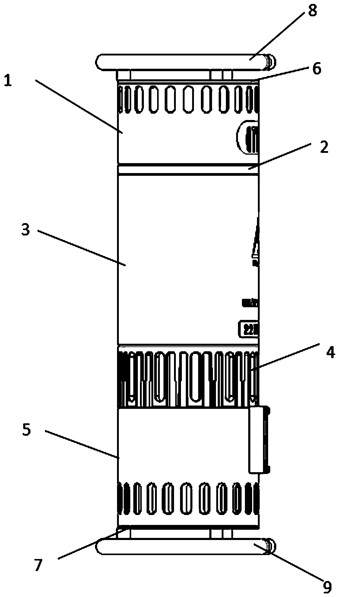
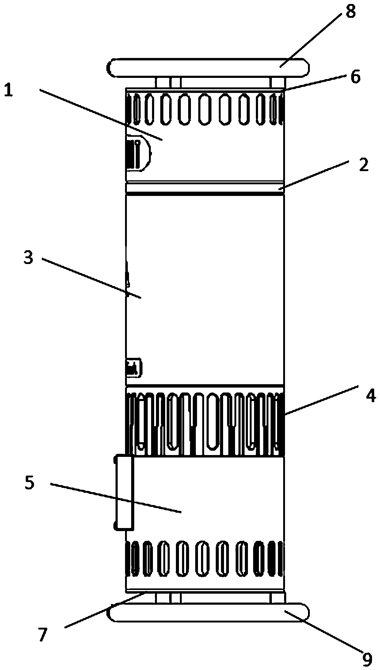
The invention belongs to the technical field of industrial X ray machines, and particularly relates to a wireless integrated X ray flaw detector. The wireless integrated X ray flaw detector comprisesa controller and a generator, wherein the controller is a PDA (Personal Digital Assistant) which controls the generator by a PLC (Programmable Logic Controller) control system through a touch screen;the generator comprises a shell constructed by detachably connecting a cover plate I, a pipe barrel I, a device board, a pipe barrel II, a pipe barrel III, a pipe barrel IV and a cover plate II in sequence; through holes of unified sizes are uniformly formed in the upper part of the barrel wall of the pipe barrel I to dissipate heat; a circuit control board, a power supply and a wireless transceiver are detachably connected in the pipe barrel I; the circuit control board is used for controlling a centrifugal fan and the primary stage of a fly-back transformer, and detecting current of a pressure sensor, a temperature sensor, a temperature relay and an X ray tube; the wireless transceiver is used for receiving and transmitting a signal of the controller. The wireless integrated X ray detection machine disclosed by the invention has the advantages of high efficiency, high heat dissipation speed, insusceptibility to interference, adjustable parameters, portability and the like.

Description

technical field [0001] The invention belongs to the technical field of industrial X-ray machines, and in particular relates to a wireless integrated X-ray flaw detector. Background technique [0002] The principle of X-ray flaw detector is a non-destructive inspection method that uses the characteristics of X-rays to penetrate substances and have attenuation in substances to find defects in them. X-rays can check the internal defects of metal and non-metal materials and their products. For example, volumetric defects such as pores, slag inclusions, and incomplete penetration in welds. With the development of science and technology, X-ray flaw detectors are rapidly applied to industries such as national defense, aerospace and ship oil. [0003] The X-ray flaw detector invented at first uses oil as the insulating medium and is heavy in weight. The controller is composed of loose parts, which is large in size and cumbersome to operate. After several technological innovations,...

Claims


Application Information

Patent Timeline
IPC IPC(8): G01N23/18
CPCG01N23/18G01N2223/646G01N2223/1016G01N2223/04
Inventor 夏远柱朱军马鑫樊永锋法娜伊周晓曦
Owner 丹东市祯晟科技有限公司
Learn More