
Composite filter tank for internal electrolysis and denitrification, and application thereof

A technology of denitrification and internal electrolysis, which is applied in anaerobic digestion treatment, chemical instruments and methods, water/sludge/sewage treatment, etc., can solve the problems of low synchronous denitrification and phosphorus removal efficiency, difficult backwashing, and operating costs Increase and other problems, to achieve the effect of improving biodegradability, good purification effect, and improving efficiency

Inactive Publication Date: 2018-05-04
HOHAI UNIV
View PDF5 Cites 12 Cited by
  • Summary
  • Abstract
  • Description
  • Claims
  • Application Information

AI Technical Summary

Problems solved by technology

[0006] The technical problem to be solved: on the one hand, the present invention is to solve the problem that the synchronous denitrification and phosphorus removal efficiency of the existing deep bed filter is not high and the operation process requires the addition of external carbon sources, which causes a substantial increase in operating costs; on the other hand, it is to solve After a period of operation of the deep bed filter, the filter material is easy to harden and not easy to backwash. To provide an internal electrolytic denitrification composite filter and its application

Method used


Image

  • Composite filter tank for internal electrolysis and denitrification, and application thereof
  • Composite filter tank for internal electrolysis and denitrification, and application thereof
  • Composite filter tank for internal electrolysis and denitrification, and application thereof

Examples


Embodiment 1

[0036] like figure 1As shown, an internal electrolytic denitrification composite filter, the filter includes a water distribution area 2, an iron-carbon doped area 4, a filler area 5, a supporting layer 6 and a water collection area 8 from top to bottom. The iron-carbon doped area 4, the filling area 5, the support layer 6 and the top of the water collection area 8 are all provided with a perforated water collection plate 7, and the bottom of the water collection area 8 is provided with a funnel-shaped slope with a slope of 5%; The upper part of the area is provided with a water inlet 1, and the lower part is provided with a backwash water outlet 3; the bottom of the catchment area is provided with a water outlet 10, a backwash water inlet 9 and a disturbance water inlet 11. The filler in the filler area 5 is ceramsite, and the filler in the iron-carbon doped area 4 is a mixture of iron-carbon and ceramsite. The filter tank is 1.2m high and 0.6m in diameter, wherein the thick...

Embodiment 2

[0047] In order to obtain the optimal position of iron-carbon doping, the present invention respectively doped 10% of iron-carbon in the upper, middle and lower parts of the device to obtain the optimal data. In Experimental Example 2, iron-carbon is doped in the first third of the device filler, in Experimental Example 3, iron-carbon is doped in the middle third of the device filler, and in Experimental Example 4, iron-carbon is doped in the rear third of the device filler.

[0048] As a comparison, in this embodiment, Experimental Example 1 is added, in which the matrix layer is not doped with iron carbon, and other experimental parameters are the same as those in Experimental Examples 2-4. Table 1 shows the iron-carbon doping conditions of experimental examples 1-4.

[0049] Table 1 Iron-carbon doping

[0050] Experimental serial number

1

2

3

4

stromal layer

none

10% Iron Carbon for the first third

Middle third 10% iron carbon

R...

Embodiment 3

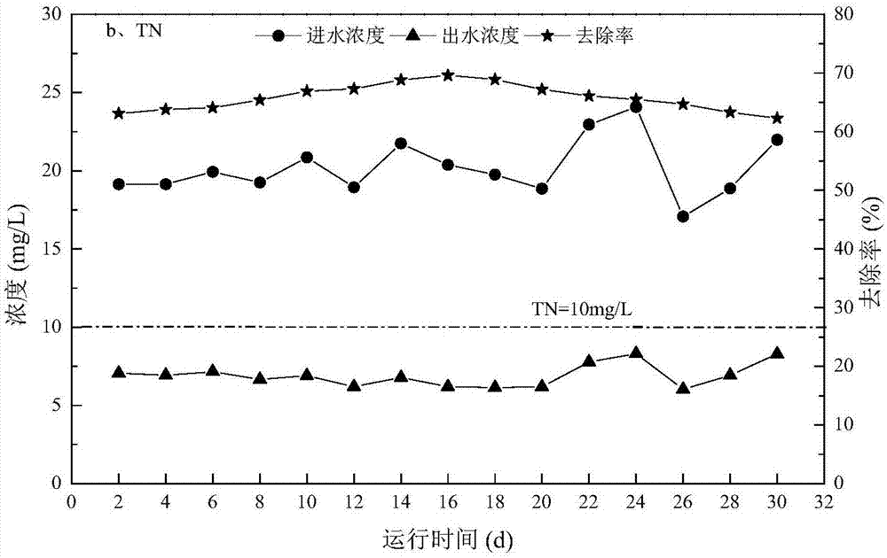
[0056] After the membrane was installed, the simulated tail water was introduced into the internal electrolytic denitrification composite filter device. The simulated tail water is shown in Table 1, and the C / N ratio was controlled at about 2. The HRT is set to 1h, the test period is 30d, and no carbon source is added. This embodiment is the same as Embodiment 1, and the water intake all adopts the water pump to lift and pressurize the water intake. After treatment, all effluent indicators are better than the special discharge limit in GB18918-2002 "Pollutant Discharge Standards for Urban Sewage Treatment Plants (2015 Draft for Comment)", that is, COD≤30mg / L, ammonia nitrogen≤1.5mg / L , TN≤10mg / L, TP≤0.3mg / L. After the above treatment, the water quality of its inlet and outlet water is shown in Table 3. Figure 2 to Figure 5 .

[0057] Table 3 Influent and effluent water quality and removal rate

[0058]


PUM

PropertyMeasurementUnit
Thicknessaaaaaaaaaa
Thicknessaaaaaaaaaa
Particle sizeaaaaaaaaaa

Abstract

The invention relates to a composite filter tank for internal electrolysis and denitrification, and application thereof. The filter tank sequentially comprises a water distribution area, an iron-carbon doping area, a filler area, a supporting layer and a water collecting area from top to bottom, wherein perforating and water collection plates are respectively arranged on the top parts of the iron-carbon doping area, the filler area, the supporting layer and the water collecting area; a funnel-shaped slope with the gradient being 5 percent is arranged on the bottom part of the water collectionarea; a water inlet is formed in the upper part of the water distribution area; a back washing water outlet is formed in the lower part of the water distribution area; a water outlet, a back washing water inlet and a disturbance water inlet are formed in the bottom part of the water colleting area. According to the composite filter tank for internal electrolysis and denitrification, and the application thereof provided by the invention, on one hand, the problems that an existing deep-bed filter tank is low in simultaneous phosphorus and nitrogen removal efficiency and the operation cost is greatly increased since an external carbon source needs to be fed during an operation process is solved, and on the other hand, the problem that after the deep-bed filter tank is operated for a certain time, a filter material is easy to harden so as not to be easy to back wash is solved.

Description

technical field [0001] The invention relates to the field of sewage treatment, in particular to an internal electrolytic denitrification compound filter treatment method for denitrification and phosphorus removal of tail water of a treatment plant. Background technique [0002] With the change of people's lifestyle, urban domestic sewage in many places, especially in the south, is showing a low-carbon trend. After the sewage is treated by the biochemical treatment unit of the sewage plant, the residual organic carbon sources in the tail water are mainly humic acid, fulvic acid, amino acids and surfactants. less than 0.2), it is difficult to be degraded and utilized by microorganisms. At the same time, the content of TN in the tail water is high, which is a special kind of sewage with a low carbon-to-nitrogen ratio (BOD 5 / TN value is less than 1), and NO 3 -N is the main component of nitrogen in tail water, accounting for more than 80% of TN. Under the condition of low-c...

Claims


Application Information

Patent Timeline
IPC IPC(8): C02F9/14C02F101/10C02F101/38
CPCC02F1/46104C02F1/46176C02F3/28C02F3/34C02F2101/105C02F2101/38
Inventor 郑晓英金梦琦陈卫周翔周橄卢丹张远邵晓瑶
Owner HOHAI UNIV
Learn More