Waste heat recovery and energy conservation integrated steam oven
A waste heat recovery and steam technology, which is applied in the field of steam stoves, can solve problems such as heat loss of steam stoves, and achieve the effects of improving utilization, efficiency, and thermal efficiency
- Summary
- Abstract
- Description
- Claims
- Application Information
AI Technical Summary
Problems solved by technology
Method used
Image
Examples
Embodiment 1
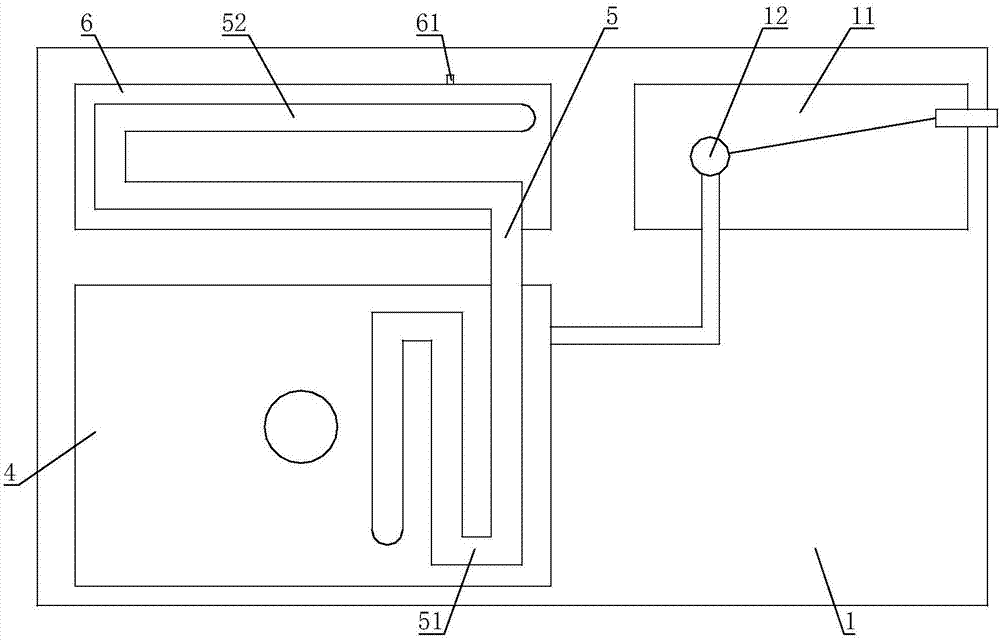
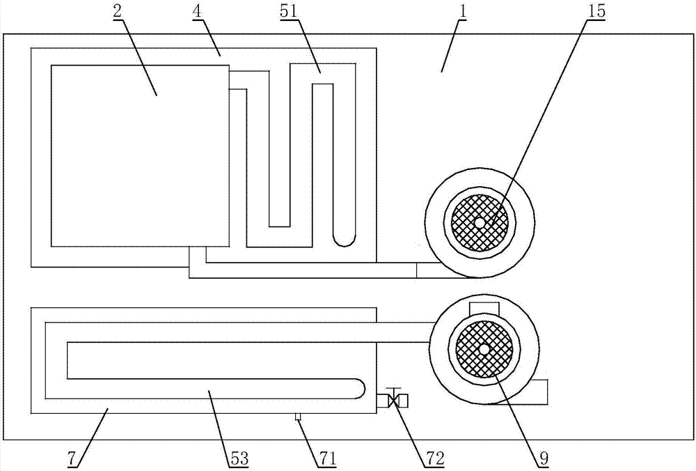
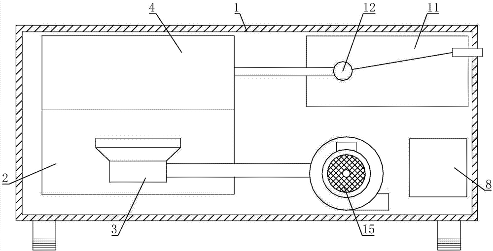
[0037] Such as figure 1 , figure 2 , image 3As shown, the present invention includes a steam stove main body 1, a combustion chamber 2 is arranged in the steam stove main body 1, and a burner 3 is installed in the combustion chamber 2; it is characterized in that, the steam stove main body 1 is also provided with a steam chamber 4 and a The steam chamber 4 is provided with a steam outlet, the smoke outlet of the combustion chamber 2 is connected with a heat conduction mechanism 5, the heat conduction mechanism 5 passes through the steam chamber 4, and after the heat conduction mechanism 5 passes through the steam chamber 4, press several The waste heat exchange cavities pass through several waste heat exchange cavities sequentially; the last waste heat exchange cavity along the flow direction of the waste gas in the heat conduction mechanism 5 is connected with a tap water inlet pipe; the main body 1 of the steam stove is also equipped with a replenishing water tank 11 , T...
Embodiment 2
[0043] On the basis of Embodiment 1, two waste heat exchange cavities are arranged in the main body 1 of the steam stove. The cavity 7 is connected; the heat conduction mechanism 5 includes a high-temperature exhaust gas heat-conducting pipe 51, a medium-temperature exhaust gas heat-conducting pipe 52, and a low-temperature exhaust gas heat-conducting pipe 53 connected in sequence. In the waste heat exchange chamber 6 , the low-temperature waste gas heat conduction pipe 53 is arranged in the low-temperature waste heat exchange chamber 7 ; the tap water inlet pipe is connected to the low-temperature waste heat exchange chamber 7 .
[0044] The high-temperature exhaust gas exchanges heat with the steam chamber 4 through the high-temperature exhaust gas heat pipe 51, and the high-temperature exhaust gas at 500°C to 600°C becomes medium-temperature exhaust gas at 140°C or higher. The medium-temperature exhaust gas exchanges heat with the medium-temperature waste heat exchange cham...
Embodiment 3
[0046] On the basis of Embodiment 1 or Embodiment 2, the wall thickness of the high-temperature exhaust gas heat-conducting pipe 51 , the wall thickness of the medium-temperature exhaust gas heat-conducting pipe 52 , and the wall thickness of the low-temperature exhaust gas heat-conducting pipe 53 are successively reduced.
[0047] The wall thickness of the high-temperature exhaust gas heat-conducting pipe 51, the wall thickness of the medium-temperature exhaust gas heat-conducting pipe 52, and the wall thickness of the low-temperature exhaust gas heat-conducting pipe 53 are successively reduced, so that each section of the heat-conducting tube can adapt to the temperature of the exhaust gas inside, ensuring that each section of the heat-conducting tube has Suitable heat resistance. In the case of ensuring that the heat-conducting tube has sufficient heat resistance, the heat-conducting tubes are set to have different wall thicknesses, so that the wall thickness of the heat-con...
PUM
 Abstract
Description
Claims
Application Information
 - R&D
- Intellectual Property
- Life Sciences
- Materials
- Tech Scout
- Unparalleled Data Quality
- Higher Quality Content
- 60% Fewer Hallucinations
Browse by: Latest US Patents, China's latest patents, Technical Efficacy Thesaurus, Application Domain, Technology Topic, Popular Technical Reports.
© 2025 PatSnap. All rights reserved.Legal|Privacy policy|Modern Slavery Act Transparency Statement|Sitemap|About US| Contact US: help@patsnap.com


