Method and equipment for reducing dioxin in smoke emitted in waste incineration

A waste incineration and dioxin technology, applied in the direction of combustion methods, greenhouse gas reduction, lighting and heating equipment, etc., can solve the problems of short service life of equipment, high energy consumption, and unreasonable use of heat, and achieve high heat recovery efficiency , low energy consumption and simple structure

Pending Publication Date: 2018-04-27
CHENGDU INTERMENT TECH
View PDF9 Cites 1 Cited by
  • Summary
  • Abstract
  • Description
  • Claims
  • Application Information

AI Technical Summary

Problems solved by technology

[0012] The main purpose of the present invention is to provide a method and equipment for reducing dioxins in the flue gas emitted by waste incineration, so as to solve the problems of short service life, high energy consumption and unreasonable use of heat in the prior art

Method used


Image

  • Method and equipment for reducing dioxin in smoke emitted in waste incineration
  • Method and equipment for reducing dioxin in smoke emitted in waste incineration

Examples


Embodiment 1

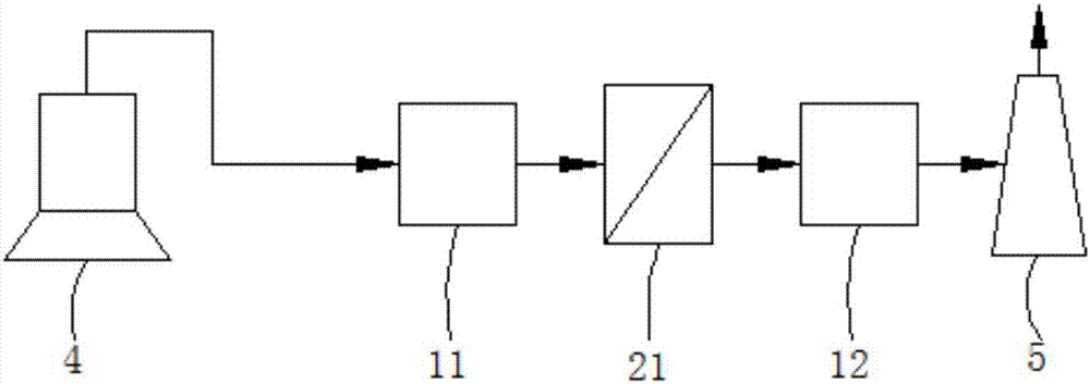
[0047] like figure 1 The shown device for reducing dioxins in the flue gas emitted by waste incineration includes a first waste heat recovery device 11, a first filter device 21 and a second waste heat recovery device sequentially arranged between the gas outlet of the incinerator 4 and the chimney 5 Recycling equipment 12.

[0048] The first waste heat recovery device 11 is a waste heat recovery device for processing the flue gas of the incinerator 4 to obtain the first flue gas with a temperature of 450°C-500°C.

[0049] The filter material of the first filtering device 21 is a sheet made of a solid solution alloy, a metal element with a face-centered cubic structure, or a metal porous material with a body-centered cubic structure as a matrix phase, and its thickness is 1mm, and the porosity is 60%, with an average pore size of 10 μm; the first filter device 21 filters the first flue gas to obtain a second flue gas with a fly ash content ≤ 10 mg / Nm3.

[0050] The second wa...

Embodiment 2

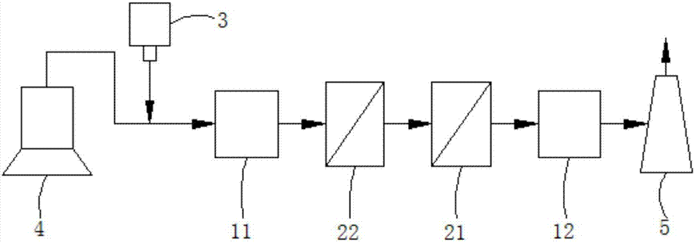
[0053] like figure 2 The shown device for reducing dioxins in the flue gas emitted by waste incineration includes a powder feeder 3, a first waste heat recovery device 11, and a second filter device 22 arranged in sequence between the gas outlet of the incinerator 4 and the chimney 5 , the first filter device 21 and the second waste heat recovery device 12 .

[0054] The function of the powder adding device 3 is to add modified powder to the flue gas, and the modified powder is diatomite with a particle size of 40 μm.

[0055] The first waste heat recovery device 11 is a waste heat recovery device for processing the flue gas of the incinerator 4 to obtain the first flue gas with a temperature of 450°C-500°C.

[0056] The filter material of the second filter device 22 is a metal alloy, its pore size is larger than that of the filter material of the first filter device 21, and the retention rate of the fly ash in the flue gas is ≥85%, and the modified powder The interception ...


PUM

PropertyMeasurementUnit
Thicknessaaaaaaaaaa
Average pore sizeaaaaaaaaaa
Apertureaaaaaaaaaa

Abstract

The invention discloses a method and equipment for reducing dioxin in smoke emitted in waste incineration. The method comprises the following steps: (1) reducing the temperature of the smoke to 450 to800 DEG C by adopting first afterheat recycling equipment, and treating the smoke by using the first afterheat recycling equipment to obtain first smoke; (2) filtering the first smoke at a temperature larger than or equal to 350 DEG C by adopting first filtration equipment, and making the first smoke pass through a filter material of the first filtration equipment to obtain second smoke of whichthe flying dust content is smaller than or equal to 20 mg / Nm<3>; and (3) reducing the temperature of the second smoke to 200 DEG C or below 200 DEG C by adopting second afterheat recycling equipment,and treating the second smoke by using the second afterheat recycling equipment to obtain exhaust smoke which can be directly exhausted, wherein the filter material of the first filtration equipment is a sheet composed of a metal porous material which takes a metal element of solid solution alloy and a face-centered cubic structure or the metal element of a body-centered cubic structure as a matrix phase.

Description

technical field [0001] The invention relates to the technical field of waste incineration flue gas treatment, in particular to a method and equipment for reducing dioxins in the flue gas emitted by waste incineration. Background technique [0002] Dioxin is a kind of chlorinated organic compound, which is the general name of polychlorinated dibenzodioxin, polychlorinated dibenzofuran and its homologues. Its toxicity is 1000 times that of potassium cyanide. The national standard "Pollution Control Standards for Hazardous Waste Incineration (GB18484-2001)" stipulates that the dioxin emission standard is 0.5ng TEQ / Nm 3 (Ng TEQ value per standard cubic meter). The full combustion of garbage at a higher temperature can decompose dioxins, but some studies have shown that when the temperature ranges from 250°C to 300°C, dioxin precursors will decompose under the catalysis of fly ash. Re-synthesis of dioxins. Therefore, rapid cooling is adopted in the flue gas purification sectio...

Claims


Application Information

Patent Timeline
IPC IPC(8): F23G5/44F23J15/06F23J15/02
CPCF23G5/44F23J15/025F23J15/06B01D2273/20Y02E20/30
Inventor 高麟汪涛袁林
Owner CHENGDU INTERMENT TECH
Why Eureka
Try Eureka