
Heat energy recycling method and device for molten metallurgical slag

A technology for heat energy recovery and metallurgical slag, which is applied in waste heat treatment, energy efficiency improvement, lighting and heating equipment, etc. It can solve the problems of low supply air temperature and energy consumption, so as to increase the heat transfer distance and increase the dispersion effect. , the effect of increasing the heat transfer area and efficiency

Active Publication Date: 2018-03-16
TIANJIN UNIV
View PDF7 Cites 3 Cited by
  • Summary
  • Abstract
  • Description
  • Claims
  • Application Information

AI Technical Summary

Problems solved by technology

However, since the preheating temperature of blast furnace gas and combustion-supporting air is limited by the exhaust gas temperature of the hot blast stove and the working temperature of the heat pipe, there are generally problems of low air supply temperature and energy consumption.

Method used


Image

  • Heat energy recycling method and device for molten metallurgical slag
  • Heat energy recycling method and device for molten metallurgical slag
  • Heat energy recycling method and device for molten metallurgical slag

Examples


Embodiment 1

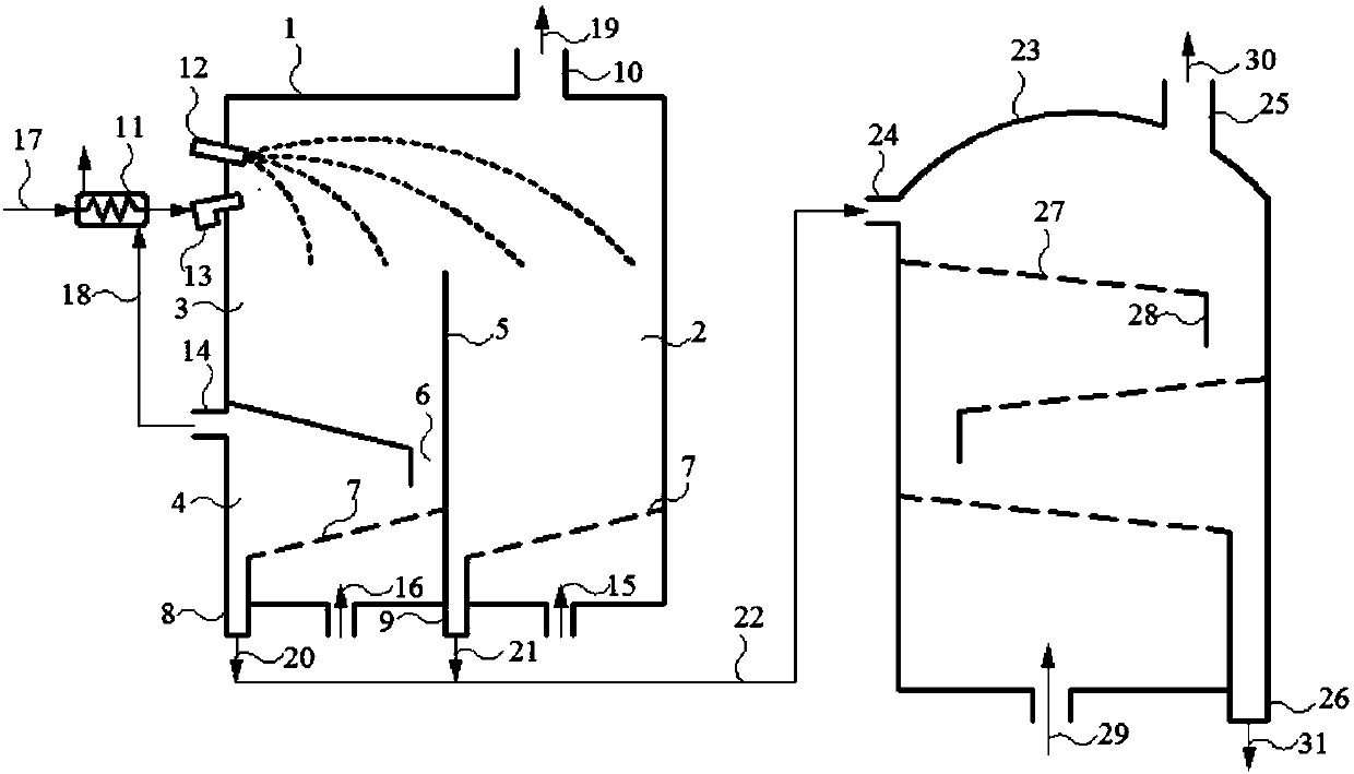
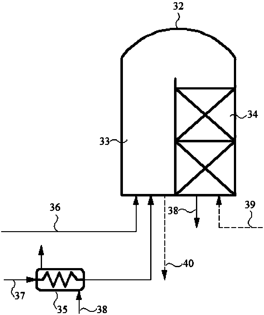
[0048] This embodiment is a heat recovery and utilization scheme for molten ironmaking slag, which includes two parts of the process: molten metallurgical slag granulation and moving bed heat exchange cooling to produce high-temperature air and the use of full amount of medium-temperature hot air for the hot blast furnace system. Such as figure 1 As shown, the molten metallurgical slag 12 at 1500°C flows into the granulation device 1 through the feed inlet, is blown away by the granulation airflow 17 injected from the granulation airflow injection port 13, and settles in a parabola. Due to the small air flow disturbance, the small granulated particles 21 cross the partition baffle 5 and blow to the remote settlement area 2, and the small granulated rapid cooling medium 15 is blown in from the bottom to promote the rapid cooling of the small granulated particles 21 to below 900°C , drop along the perforated bed layer plate 7 to the small particle outlet 9 and discharge; the sma...

Embodiment 2

[0054] This embodiment is a heat recovery and utilization scheme for molten steelmaking slag, including two parts of the process: molten metallurgical slag granulation and rotary heat exchange cooling to produce high-temperature air part and component high-temperature air-pre-combustion matching utilization method for hot blast stove system part. Such as Figure 4 As shown, the molten metallurgical slag 12 at 1500°C flows into the granulation device 1 through the feed inlet, is blown away by the granulation airflow 17 injected from the granulation airflow injection port 6, and settles in a parabola. Due to the great influence of the turbulent air flow, the large-grained granules 20 cross the partition baffle 5 and blow to the distant settlement area 2, enter the secondary granulator 4, and contact the secondary granulation cooling medium 16 for secondary granulation. The temperature is lowered to below 900°C and discharged from the large particle outlet 8; water is used as th...

Embodiment 3

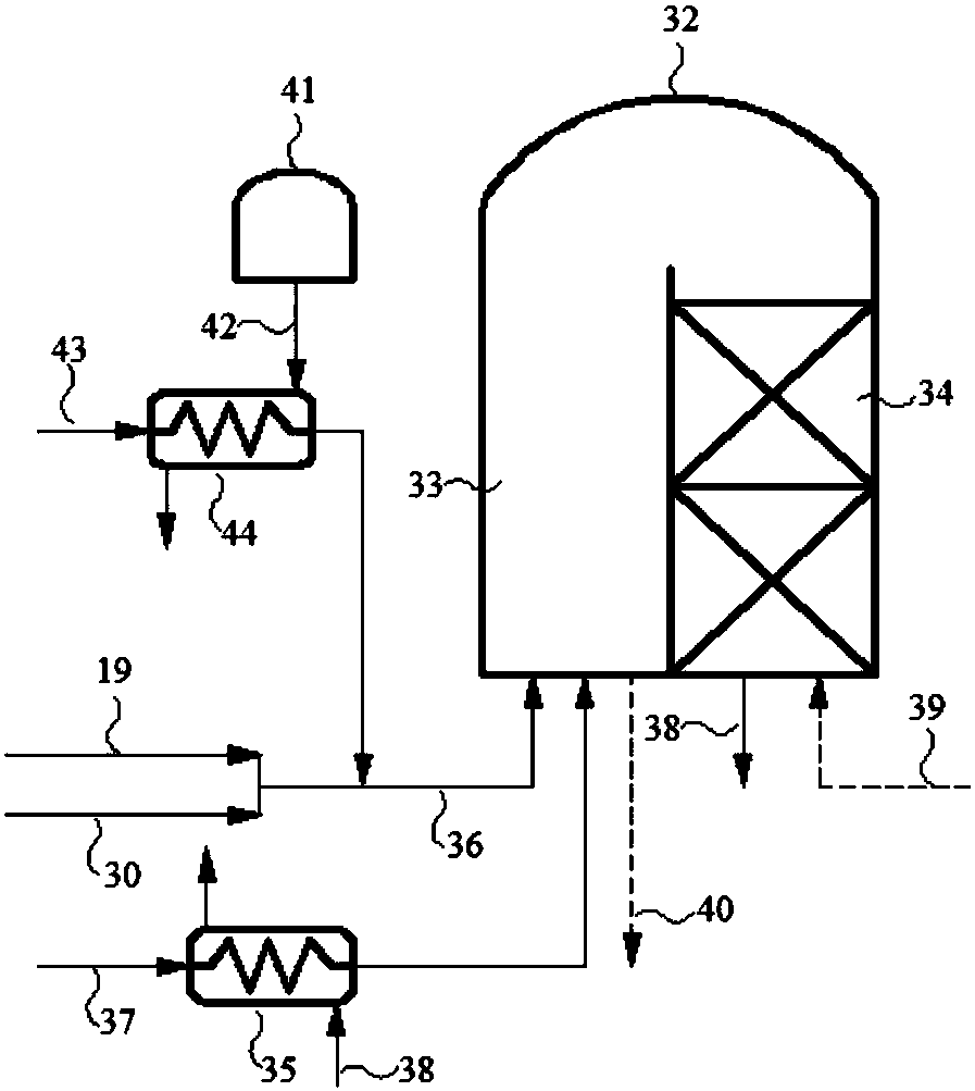
[0061] This embodiment is a heat energy recovery scheme for molten metallurgical slag in nonferrous metallurgy. The granulation and heat energy recovery of molten metallurgical slag are the same as in Example 1, except that high-temperature air is used to preheat the hot air that is pressured to the smelting furnace, such as Figure 5 shown. The smelting air 39 is heated by the mixed air flow of the granulated hot gas 19 and the heat exchange hot gas 30 through the metallurgical blast heat exchanger 45, and the temperature rises to about 400-500°C, and then passes into the cold air inlet of the hot blast stove 32, and the heat storage chamber The 34 checker bricks complete further heat exchange, and the hot air 40 for smelting above 1200°C is discharged from the hot air outlet, and sent into the metallurgical furnace to participate in smelting.

[0062] The hot air generated by heat recovery of molten ironmaking slag is directly used for preheating of metallurgical blast, whic...


PUM


Abstract

The invention relates to a heat energy recycling method and device for molten metallurgical slag. The heat energy recycling method for the molten metallurgical slag is at least composed of the moltenmetallurgical slag heat energy recycling process that heat energy is recycled from the molten metallurgical slag to generate high-temperature gas and the heat energy utilization process. Heat energy recycling of the molten metallurgical slag is at least composed of the molten metallurgical slag granulating process that the molten metallurgical slag flowing out from a metallurgical furnace is cooled rapidly to generate metallurgical slag granulated particles and the granulated particle cooling process of further cooling the metallurgical slag granulated particles obtained in the metallurgical slag granulating process. The molten metallurgical slag is blown away through granulating airflow to form the metallurgical slag granulated particles, and the metallurgical slag granulated particles fall and are collected in a large-particle area and a small-particle area which are divided in the particle flying-out direction. The small particles directly enter into the granulated particle coolingprocess or other heat-exchange processes, the large particles enter into the secondary granulating process, and the mode that air, or water or a mixture of the water and the air makes direct contact with the large particles is adopted during secondary granulating. Material recycling of the molten metallurgical slag and high-value utilization of the heat energy are achieved, and the method is provided for metallurgical energy saving and emission reduction, consumption reduction and effect increasing.

Description

technical field [0001] The invention relates to a high-grade, low-cost heat energy recovery method and device for molten metallurgical slag and its high-value utilization, especially the granulation process of molten metallurgical slag, and the high-temperature gas generated by the granulated particles is used to increase the air temperature of the hot blast furnace and save energy. It can be used as fuel or as other heat sources, and belongs to the field of metallurgical energy, energy recycling and environmental protection. Background technique [0002] In the process of ironmaking, steelmaking and pyrometallurgy in the metallurgical industry, a large amount of high-temperature molten metallurgical slag will be produced, such as blast furnace slag and steel slag produced in ironmaking furnaces, and copper slag, lead slag and zinc slag produced in nonferrous metal smelting etc. The furnace temperature is usually around 1400-1600°C, and 350-480kg of metallurgical slag can be...

Claims


Application Information

Patent Timeline
Patent Type & Authority Applications(China)
IPC IPC(8): F27D17/00F27D3/15C21B3/08
CPCC21B3/08F27D3/15F27D17/004Y02P10/20Y02P10/25
Inventor 张书廷童璐
Owner TIANJIN UNIV
Learn More