Eureka AIR delivers breakthrough ideas for toughest innovation challenges, trusted by R&D personnel around the world.

Two-cycle aviation heavy oil piston engine cylinder sleeve inner wall laser micro-texturing structure

A technology of engine cylinder and micro-modelling, which is applied in the direction of engine components, machines/engines, pistons, etc. It can solve the problems that the lines cannot be adjusted according to the needs, and the independent pits cannot be processed, etc., and achieve small linear expansion coefficient, heat resistance and Good casting performance and improved sealing effect

Active Publication Date: 2018-02-13
北京领动国创科技有限公司
View PDF12 Cites 6 Cited by
  • Summary
  • Abstract
  • Description
  • Claims
  • Application Information

AI Technical Summary

Problems solved by technology

Cylinder liner surface treatment technologies mainly include mechanical honing and laser micro-modeling. Mechanical honing was applied earlier and the process is mature. Although the processing equipment is simple and low in cost, the obtained lines cannot be adjusted according to needs, and independent pits cannot be processed.

Method used


Image

  • Two-cycle aviation heavy oil piston engine cylinder sleeve inner wall laser micro-texturing structure
  • Two-cycle aviation heavy oil piston engine cylinder sleeve inner wall laser micro-texturing structure
  • Two-cycle aviation heavy oil piston engine cylinder sleeve inner wall laser micro-texturing structure

Examples


Embodiment Construction

[0054] The present invention will be further described below in conjunction with the accompanying drawings and specific embodiments.

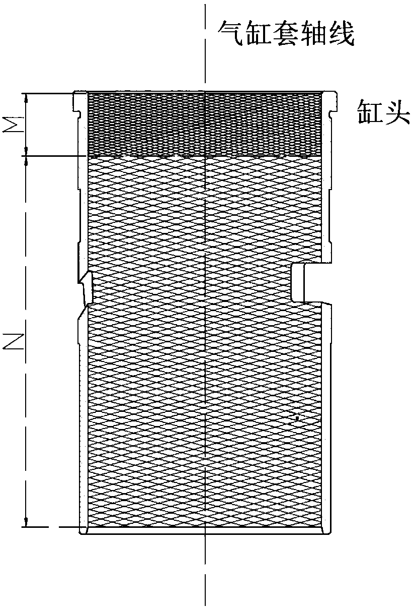
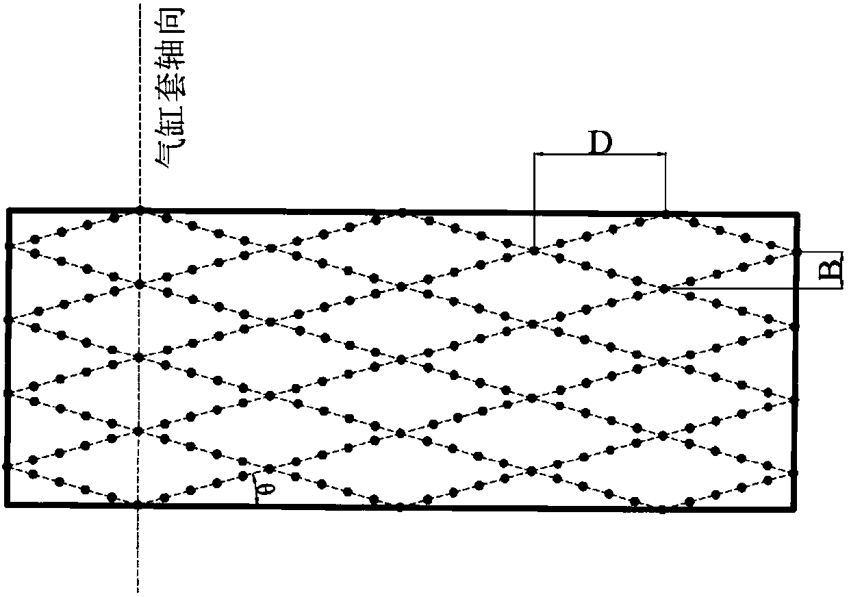
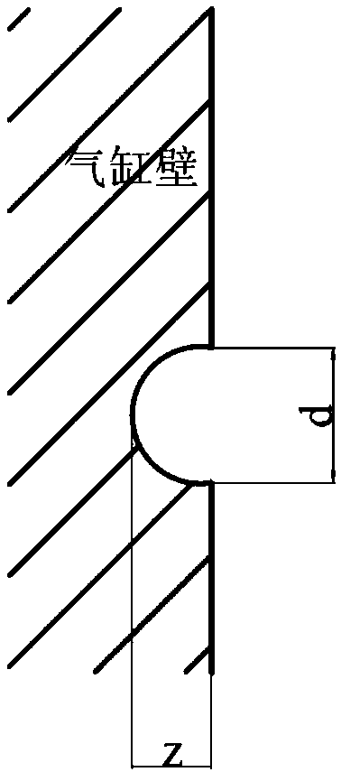
[0055] Such as figure 1 As shown in -2, the laser micro-modeling structure of the inner wall of the engine cylinder liner disclosed by the present invention, the cylinder includes the M area of ​​the cylinder liner head and the N area of ​​the cylinder block. Sparse micro-modeling; the micro-modeling adopts a spiral pattern with a small inclination relative to the plane perpendicular to the axial direction of the cylinder. The pits are mesh points, and there are multiple pits between adjacent mesh points. The angle θ between the lines and the axial direction of the cylinder, that is, the cylinder circumferential direction, is between 10°-15°. The vertical distance B of the pattern point in the axial direction of the cylinder liner is 1-1.3mm, the vertical distance D of the adjacent pattern point in the cylinder liner circumferential direction ...


PUM

PropertyMeasurementUnit
Pit depthaaaaaaaaaa

Abstract

The invention discloses a two-cycle aviation piston engine drive lubrication cylinder sleeve inner wall laser micro-texturing structure design method. The method comprises the steps that firstly, through analysis modeling on boundary lubrication of the two friction pairs including a piston ring-a cylinder sleeve and a piston skirt-the cylinder sleeve which are abraded most severely, micro texturesfollowing the optimal arranging rules are arranged on the surface of the cylinder sleeve in a targeted mode, pits of the micro textures are filled with various abrasive particles in the up-down strokes of a piston and the piston ring, the cylinder sleeve is prevented from being damaged during pulling, and accordingly, the service lives of the cylinder sleeve and an engine comprising the cylindersleeve are prolonged; and secondly, the micro textures following the optimal arranging rules are utilized for organizing motion of lubricating oil film, the oil film is prevented from being broken, the velocity of motion of the lubricating oil film in the axial direction of an air cylinder is decreased, the component velocity in the circumferential direction of the piston ring is increased, thus,the amount of lubricating oil entering a combusting chamber is decreased, and consumption of the lubricating oil is reduced. Meanwhile, the flow rate of the oil film in the circumferential direction of the piston ring is increased, lubrication is improved, the airtightness of a piston ring set is improved simultaneously, and consumption of the lubricating oil is reduced.

Description

technical field [0001] The invention relates to the field of processing the surface topography of a cylinder liner of a two-stroke aviation heavy oil piston engine, in particular to a laser surface micro-modeling structure of the cylinder liner of an aviation piston engine. Background technique [0002] The two-stroke aviation heavy oil piston engine is the "heart" of the aircraft. The gas generated by the compression combustion of heavy oil in the cylinder pushes the piston to reciprocate along the axis of the cylinder liner. output torque. Because it is a two-stroke engine, it has compact structure, light weight, and large heat load. During this process, the wear between the piston ring set and the cylinder liner and the piston skirt and the cylinder liner are the two most severely worn pairs of friction in the engine cylinder assembly. Vice, under the conditions of high temperature, high pressure, metal shavings, solid carbon particles and corrosive media produced by ins...

Claims


Application Information

Patent Timeline
IPC IPC(8): F02F1/20F02F3/00F02F5/00
CPCF02F1/20F02F3/00F02F5/00
Inventor 周煜杜发荣蔺红鹏李果闵敏
Owner 北京领动国创科技有限公司
Why Eureka
Eureka Blog
Learn More