Radially-adjustable three-jaw self-centering spindle clamp

A self-centering and mandrel technology, applied in the direction of the chuck, can solve the problems affecting the accuracy of the experimental results, the low rigidity of the disc specimen, and increasing the experimental cost, and achieves a simple structure, good clamping rigidity, and clamping. Efficient effect

Pending Publication Date: 2018-02-06
TIANJIN UNIV OF TECH & EDUCATION TEACHER DEV CENT OF CHINA VOCATIONAL TRAINING & GUIDANCE
View PDF0 Cites 0 Cited by
  • Summary
  • Abstract
  • Description
  • Claims
  • Application Information

AI Technical Summary

Problems solved by technology

When clamping this kind of specimen, if the clamping contact surface is too small, it will be easily deformed under the action of cutting force due to the low rigidity of the disc specimen, which will seriously affect the accuracy of the experimental results. If the clamping contact surface is too large , the part that can be cut is too small, resulting in material waste and increasing the cost of the experiment

Method used


Image

  • Radially-adjustable three-jaw self-centering spindle clamp

Examples


Embodiment 1

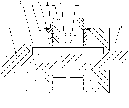
[0017] Mandrel 1, flat key 2, adjusting disc body 3, small bevel gear 4, large bevel gear 5, adjusting claw 6, supporting claw 7, fastening bolt 8 and fastening nut 9, see figure 1 . The mandrel 1 is fixed on the machine tool through the lathe chuck. There is a keyway on the mandrel. The flat key 2 is used to fix the position of the adjustment disc body 3. The adjustment square hole on the small bevel gear 4 is used to drive the large bevel gear 5. To adjust the position of the adjusting claw 6, the supporting claw 7 is fixed on the adjusting claw by the fastening bolt, and the fastening position of the supporting claw is adjustable, which can effectively increase the adjustment range, and the position of the right adjusting disc is adjusted by the fastening nut to clamp Workpieces, realizing fast and reliable clamping of thin-walled disk parts.


PUM


Abstract

The invention relates to an adjustable spindle clamp, and particularly relates to a radially-adjustable three-jaw self-centering spindle clamp. The spindle clamp is structurally characterized in thata spindle is fixed to a machine tool through a lathe chuck, the spindle is a stepped shaft, a key groove is formed in the spindle, and the position of an adjusting disk can be fixed through a steppedtable and a flat key. The adjusting disk has a self-centering function by using a three-jaw lathe chuck principle, and the transmission of a large bevel gear is driven by adjusting a square adjustinghole in a small bevel gear so that it can be achieved the positions of adjusting jaws are adjusted; a supporting jaw is fixed to the adjusting jaw through fastening bolts, the fastening position of the supporting jaw can be adjusted so that the adjusting range can be effectively expanded, and the obstruction to the feed path is reduced. The position of a right adjusting disk body is adjusted through a fastening nut so as to clamp a workpiece, it is achieved that a thin-plate disk-like part is quickly clamped, the clamping rigidity is ensured, and the machining quality is improved.

Description

technical field [0001] The invention is a radially adjustable three-jaw self-centering mandrel clamp. Background technique [0002] High-speed cutting has the advantages of high productivity, small cutting force, high machining accuracy, good surface quality, low production cost, and can process difficult-to-machine materials. It has been widely used in aerospace, automobile, mold and other manufacturing fields, and has become a The mainstream direction of cutting technology development. The study found that due to the change of chip shape, high-speed cutting is very different from traditional cutting in terms of cutting force, cutting temperature and tool wear, which makes the traditional cutting theory no longer applicable in high-speed machining. The study of deformation has always been an important direction in the study of high-speed cutting mechanism. At present, the orthogonal cutting experiment is still a mainstream method for the research of high-speed cutting mec...

Claims


Application Information

Patent Timeline
Patent Type & Authority Applications(China)
IPC IPC(8): B23B31/12
CPCB23B31/12
Inventor 李国和刘蒙蔡玉俊戚厚军闫辉
Owner TIANJIN UNIV OF TECH & EDUCATION TEACHER DEV CENT OF CHINA VOCATIONAL TRAINING & GUIDANCE
Why Eureka
Try Eureka