An internal combustion engine valve clamping manipulator

A technology for internal combustion engines and manipulators, applied in the field of clamping manipulators for internal combustion engine valves, can solve the problems of poor valve delivery position accuracy, affect production efficiency, and affect stability, and achieve the effects of ensuring accuracy, good clamping rigidity, and ensuring accuracy

Active Publication Date: 2016-05-04
山东省未来人才发展有限公司
View PDF8 Cites 0 Cited by
  • Summary
  • Abstract
  • Description
  • Claims
  • Application Information

AI Technical Summary

Problems solved by technology

The clamping method of the valve directly affects the stability of the conveying process, the accuracy of the conveying position, and the accuracy of positioning. The current clamping method is in the process of processing, the accuracy of the valve conveying position is poor, the positioning accuracy and repeatability of the valve are clamped Poor; large scratches; seriously affect production efficiency and product qualification rate

Method used


Image

  • An internal combustion engine valve clamping manipulator
  • An internal combustion engine valve clamping manipulator
  • An internal combustion engine valve clamping manipulator

Examples


Embodiment 1

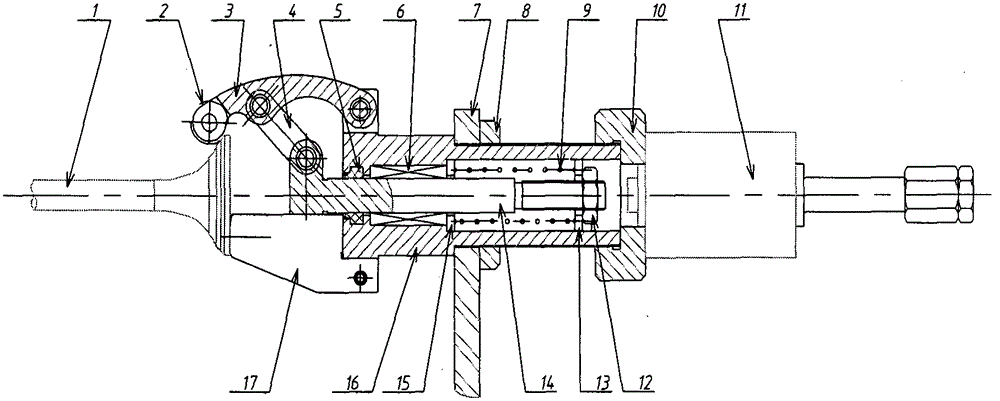
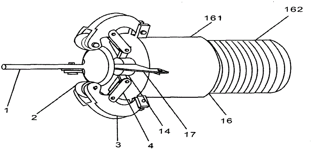
[0026] Embodiment 1: as figure 1 and 2 As shown, a clamping manipulator for an internal combustion engine valve includes a plurality of support blocks 17 and a pressing mechanism for clamping and positioning the disc plane of the valve. The disk plane is evenly distributed radially to realize the axial positioning of the valve. The pressing mechanism presses the valve on the cone surface of the valve disk to realize the radial positioning of the valve. The pressing mechanism and the support block are clamped Pressure is created, which locks the valve.

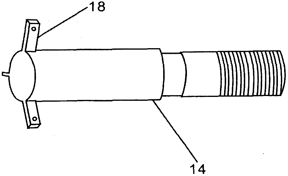
[0027] The clamping mechanism includes a clamp body 16 with a hollow cavity structure. A pull rod 14 that reciprocates along the axial direction of the clamp body is arranged in the hollow cavity of the clamp body 16. The left end of the pull rod 14 extends outside the clamp body, and is provided with There are a plurality of connection holes; the left end face of the clamp body 16 is the valve positioning end, and a pluralit...


PUM


Abstract

An internal combustion engine valve clamping manipulator is structurally characterized by comprising a plurality of supporting blocks (17) and a hold-down mechanism, wherein the supporting blocks can carry out clamping and locating on a valve retainer plane. The supporting blocks are arranged at the bottom the valve retainer plane and are evenly distributed in the radial direction of the valve retainer plane to achieve axial locating of a valve. The hold-down mechanism tightly presses the valve on an upper conical surface of a valve retainer to achieve the radial locating of the valve. Pressure is generated between the hold-down mechanism and the supporting blocks through clamping so as to fix the valve. The internal combustion engine valve clamping manipulator is high in precision of clamping and repeated locating, and free of scraping and collision in the full process of delivering, feeding and material retraction.

Description

technical field [0001] The invention relates to a manipulator for clamping an internal combustion engine valve. Background technique [0002] With the growing auto parts market, the production of valves is developing in batches and scales, so the demand for intelligence and automation in the process of valve processing is becoming stronger and stronger. The key to realizing the automation of the valve processing process is to realize the clamping, conveying and positioning of the valve. The clamping method of the valve directly affects the stability of the conveying process, the accuracy of the conveying position, and the accuracy of positioning. The current clamping method is in the process of processing, the accuracy of the valve conveying position is poor, the positioning accuracy and repeatability of the valve are clamped Poor; large scratches; seriously affect production efficiency and product qualification rate. Contents of the invention [0003] In view of the abo...

Claims


Application Information

Patent Timeline
Patent Type & Authority Patents(China)
IPC IPC(8): B25J15/10
Inventor 江金玉
Owner 山东省未来人才发展有限公司
Why Eureka
Try Eureka