Precise ball lock positioning gripping head

A positioning clip and ball lock technology, which is used in the direction of grinding workpiece supports, etc., to achieve high repeat positioning accuracy, improve work efficiency, and good clamping concentricity.

Active Publication Date: 2014-08-13
JOUDER PRECISION INDAL KUSN
View PDF5 Cites 0 Cited by
  • Summary
  • Abstract
  • Description
  • Claims
  • Application Information

AI Technical Summary

Problems solved by technology

[0005] Purpose of the invention: In order to overcome the deficiencies in the prior art, the present invention provides a precision ball lock chuck to solve the problems of fast clamping and precise positioning in the batch processing process

Method used


Image

  • Precise ball lock positioning gripping head
  • Precise ball lock positioning gripping head

Examples


Embodiment Construction

[0020] The present invention will be further described below in conjunction with the accompanying drawings.

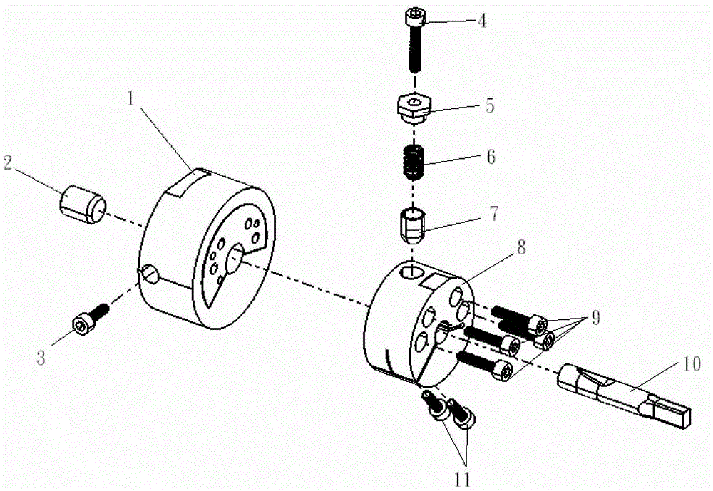
[0021] Such as figure 1 , figure 2 Shown is a precision ball lock chuck, including base ring 1, limit pin 2, limit pin locking screw 3, clamping ring 8, ball pin 7, spring 6, ball pin limit nut 5 The screw 4 is pulled out with the ball stud, and the base ring 1 and the clamping ring 8 are matched through a concave-convex step structure and coaxially fixed by a connecting screw 9 .

[0022] On the central axis of the clamping ring 8, a clamping hole communicating with the two end faces of the clamping ring 8 is provided; on the side wall of the clamping ring 8, a step hole vertically facing the clamping hole and communicating with the clamping hole is provided, The orifice end of the step hole is provided with a thread for fitting the ball stud stop nut 5, the middle end is a straight hole for fitting the ball stud 7, and the end of the hole near the clamping hole fo...


PUM


Abstract

The invention discloses a precise ball lock positioning gripping head comprising a base ring, a limit pin locking screw, a clamping ring, a ball pin, a spring, a ball pin limit nut and a ball pin extraction screw, wherein the base ring and the clamping ring are fixed coaxially through a connection screw; a clamping hole is formed in the clamping ring; a stepped hole and a through groove are formed in the side wall of the clamping ring; the ball pin limit nut is mounted on the threaded part of the stepped hole; the ball pin is mounted on the straight hole part of the stepped hole and is limited through a throat; the spring is pressed between the ball pin limit nut and the ball pin; two side walls of the through groove are locked by locking threaded pieces with opposite countersunk head holes and the clamping ring; a through hole is formed in the base ring; a vertical through hole is formed in the side wall of the base ring; the limit pin is inserted into the through hole in the side wall of the base ring; and the limit pin locking screw is screwed in a countersunk head screw hole to press the limit pin. According to the precise ball lock positioning gripping head provided by the invention, problems in quick clamping and accurate positioning during a batch process are solved.

Description

technical field [0001] The invention relates to mechanical processing technology, in particular to a fast clamping and positioning jig for a ball lock punch. Background technique [0002] At present, the processing method of a ball lock punch with a special-shaped edge is generally processed by a surface grinder: first, use a ball lock positioning jig to cut a positioning edge at the cutting edge of the workpiece; then use a punch former to clamp each The height gauge is used to level the positioning side through the height gauge; then the center of the workpiece is adjusted to process the special-shaped cutting edge. In this processing method, the processing cycle of a single workpiece is 35 to 40 minutes, and the cutting of the positioning edge, the clamping of the height gauge, the leveling of the positioning edge, and the adjustment of the workpiece center take about 8 minutes. [0003] Another processing method of the special-shaped edge ball lock punch is to use a CNC...

Claims


Application Information

Patent Timeline
Patent Type & Authority Patents(China)
IPC IPC(8): B24B41/06
Inventor 杨天文
Owner JOUDER PRECISION INDAL KUSN
Why Eureka
Try Eureka