Preparation method of membrane electrode comprising three-dimensional lyophobic negative electrode catalysis layer
A cathode catalysis and membrane electrode technology, applied in battery electrodes, circuits, fuel cells, etc., can solve the problems of increasing the cost of membrane electrode preparation, complex multi-layer membrane electrode processes, and the catalyst utilization rate needs to be further improved. Water management capacity, enhanced diffusion capacity, improved water management effectiveness
- Summary
- Abstract
- Description
- Claims
- Application Information
AI Technical Summary
Problems solved by technology
Method used
Image
Examples
Embodiment 1
[0040] The first step is to take a 4cm×4cm Nafion211 proton exchange membrane, first place it in deionized water at 80°C for 2 hours, then place it in 5% hydrogen peroxide at 80°C for 2 hours, wash it with distilled water, and wash it at 0.5 mol L -1 treated in a sulfuric acid solution at 80°C for 2 hours, and then washed with distilled water. Place the processed Nafion membrane on the mold for preparing the membrane electrode and fix it, the size of the active area is 5cm 2 , to prevent the membrane from shrinking and deforming during the spraying of the catalyst slurry;
[0041] In the second step, put the carbon nanotubes in acetone, stir at room temperature for 10 hours, filter and then place the carbon nanotubes in a 1mol / L sulfuric acid solution, stir for 10 hours at 60 degrees Celsius, filter and wash with deionized water Carbon nanotubes to neutral, dry;
[0042] In the third step, 4.2 mg of Pt / C catalyst (Johnson Matthey) with a Pt content of 60% and 25.2 mg of per...
Embodiment 2
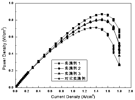
[0050] In addition to weighing the Pt / C catalyst with a Pt content of 60%, perfluorosulfonic acid polymer, carbon nanotubes and isopropanol in a mass ratio of 10:3:1:1000 for the cathode catalyst layer slurry (without adding poly Tetrafluoroethylene), other steps are the same as Example 1, and the battery activation method and test method are exactly the same as Example 1. The polarization curve of the battery is as figure 1 As shown, when the voltage is 0.7V and 0.6V, the current density can reach 800mAcm -2 and 1300mAcm -2 . The power density curve of a single cell is as figure 2 shown, the maximum power density is 801mWcm -2 .
Embodiment 3
[0052] In addition to weighing the Pt / C catalyst with a Pt content of 60%, perfluorosulfonic acid polymer, polytetrafluoroethylene emulsion and isopropanol (not Adding carbon nanotubes), other steps are the same as Example 1, and the battery activation method and test method are exactly the same as Example 1. The polarization curve of the battery is as figure 1 As shown, when the voltage is 0.7V and 0.6V, the current density can reach 800mAcm -2 and 1300mAcm -2 . The power density curve of a single cell is as figure 2 As shown, the maximum power density is 808mWcm -2 .
PUM
| Property | Measurement | Unit |
|---|---|---|
| thickness | aaaaa | aaaaa |
Abstract
Description
Claims
Application Information
 - R&D Engineer
- R&D Manager
- IP Professional
- Industry Leading Data Capabilities
- Powerful AI technology
- Patent DNA Extraction
Browse by: Latest US Patents, China's latest patents, Technical Efficacy Thesaurus, Application Domain, Technology Topic, Popular Technical Reports.
© 2024 PatSnap. All rights reserved.Legal|Privacy policy|Modern Slavery Act Transparency Statement|Sitemap|About US| Contact US: help@patsnap.com


