Bearing structural element, supporting base, connector assembly and pipe joint assembly

A technology for bearing structures and structural parts, applied in the directions of rigid brackets, pipes/pipe joints/pipes, connecting components, etc. of bearing components, which can solve the problem that the maximum load of the bottom support structure cannot be provided and the maximum design threshold is the design threshold.

Active Publication Date: 2018-01-09
CHINA COMMUNICATIONS CONSTRUCTION +3
View PDF9 Cites 0 Cited by
  • Summary
  • Abstract
  • Description
  • Claims
  • Application Information

AI Technical Summary

Problems solved by technology

[0004] The purpose of the present invention is to overcome that the general solid structure in the prior art only produces elastic deformation and plastic deformation under the action of external load, and the force transmitted to the bottom support structure is also constantly changing, which cannot provide the bottom support structure with a maximum load of In view of the above shortcomings of the design threshold, a load-bearing structure and its design method are provided, and a support for the load-bearing structure, a joint assembly using the support, and a pipe joint using the joint assembly are also provided components

Method used


Image

  • Bearing structural element, supporting base, connector assembly and pipe joint assembly
  • Bearing structural element, supporting base, connector assembly and pipe joint assembly
  • Bearing structural element, supporting base, connector assembly and pipe joint assembly

Examples


Embodiment 1

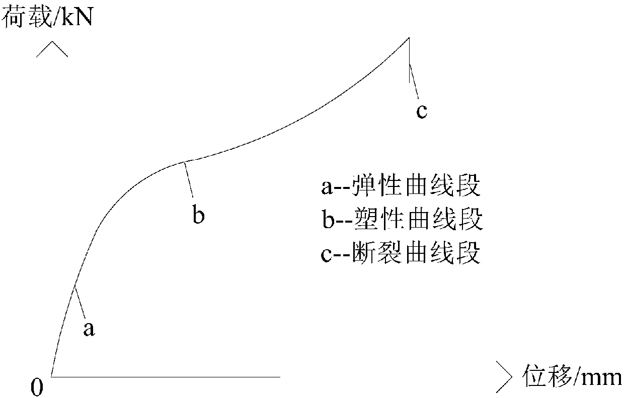
[0122] This embodiment provides a method for designing a load-bearing structural member 1. The maximum reaction force provided by the load-bearing structure 1 under an external load is its own design threshold, that is, when the external load is greater than the design of the load-bearing structural member 1. When the threshold value is reached, the load-bearing structural member 1 deforms, and at the same time, a reaction force of the design threshold value is provided. The relationship between the magnitude of the reaction load and the deformation displacement change of the load-bearing structure 1 is as follows figure 2 The shape of the middle curve c.

[0123] The load-bearing structure 1 of the present invention is an existing material structure. The design threshold refers to the maximum reaction force that the load-bearing structure 1 can provide during the deformation process when the load-bearing structure 1 is subjected to an external load. The force refers to the react...

Embodiment 2

[0133] Such as Figure 2-3 As shown, a load-bearing structural member 1, the maximum reaction force provided by the load-bearing structural member 1 under an external load is its own design threshold, that is, when the external load is less than or equal to the design threshold of the load-bearing structure 1, The load-bearing structure 1 undergoes elastic deformation or / and plastic deformation, and provides a reaction force not greater than the external load; when the external load is greater than the design threshold of the load-bearing structure 1, the load-bearing structure 1 deforms and provides a design Threshold magnitude reaction force.

[0134] The load-bearing structure 1 of the present invention is an existing material structure. The design threshold refers to the maximum reaction force that can be provided in a stable state or deformed when the load-bearing structure 1 is subjected to an external load. The reaction force refers to the reaction force provided by the lo...

Embodiment 3

[0147] This embodiment relates to the selection and testing of metal materials that meet the performance requirements of the load-bearing structure 1.

[0148] 1. Primary selection of materials:

[0149] The selection of the load-bearing structure 1 (referred to as the metal pressure-bearing column in this embodiment) needs to meet two basic conditions:

[0150] 1) The hardness is lower than steel and can be sheared by porous steel plate;

[0151] 2) Have sufficient corrosion resistance in the use environment;

[0152] Comprehensively considering the design requirements for the load and deformation of the shear key cushion and the operating environment in which the shear key cushion is working, the preliminary selected test materials for the shear key metal pressure column include copper, tin bronze, and yellow. The main mechanical properties of copper and zinc, the metal materials used in the test are shown in the following table:

[0153] Table 1 The main mechanical properties of the ...


PUM


Abstract

The invention discloses a bearing structural element, a supporting base, a connector assembly and a pipe joint assembly. The maximum counter force provided by the bearing structural element is the designed threshold of the bearing structural element under the effects of the external load, that is to say, when the external load is larger than the designed threshold of the bearing structural element, the bearing structural element deforms and provides the counter force equal to the designed threshold; the supporting base of the bearing structural element comprises at least one bearing structuralelement, and the connector assembly and the pipe joint assembly are each provided with the supporting base. The bearing structural element can effectively inhibit deformation as a rigid structural element when the external load is not high and lower than the designed threshold, can deform when the external load exceeds the designed threshold, and meanwhile provides the stable supporting counter force lower than the external load, and the bearing structural element can be applied to the supporting base, the connector assembly and the pipe joint assembly, plays a role of protecting the structure or key structural elements, and can be widely applied to the field of bridge design, building structure design, tunnel design and the like.

Description

Technical field [0001] The invention relates to the technical field of bearing materials and structures, in particular to a bearing structure, a support using the bearing structure, a joint component and a pipe joint component. Background technique [0002] Deformable solids will deform under external loads. According to the characteristics of deformation, the mechanical behavior of general solids in the force process can be divided into two distinct stages: elastic deformation and plastic deformation. Among them, elastic deformation means that when the external force is less than a certain limit (usually called the elastic limit load), after the external force that caused the deformation is removed, the solid can completely recover its original shape. This kind of recoverable deformation is called elastic deformation , The stage where the solid only produces elastic deformation is called the elastic stage; plastic deformation means that when the external force exceeds the elasti...

Claims


Application Information

Patent Timeline
Patent Type & Authority Applications(China)
IPC IPC(8): F16M7/00F16B7/00F16L25/00
CPCF16C35/02F16C41/02F16C29/002E04H9/024F16C2350/00F16C33/121F16C33/14F16C33/208F16C33/3831
Inventor 林鸣林巍刘晓东刘可心尹海卿屠柳青高纪兵刘亚平吴益元汪华文刘宇
Owner CHINA COMMUNICATIONS CONSTRUCTION
Why Eureka
Try Eureka