
Additive manufacturing method

A technology of additive manufacturing and powder, which is applied in the direction of additive manufacturing, additive processing, and improvement of process efficiency. It can solve the problems of difficult powder preparation and low yield, and achieve the effect of forming accuracy and forming quality assurance

Inactive Publication Date: 2017-12-15
ADVANCED FOR MATERIALS & EQUIP
View PDF9 Cites 28 Cited by
  • Summary
  • Abstract
  • Description
  • Claims
  • Application Information

AI Technical Summary

Problems solved by technology

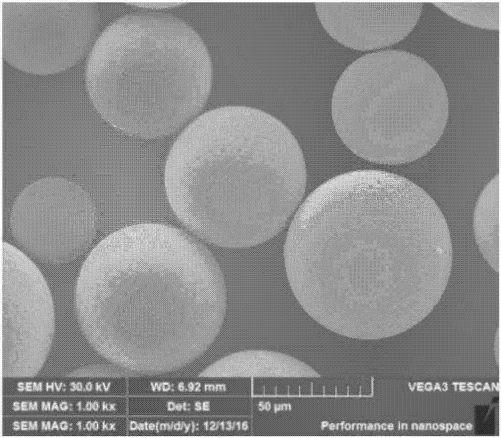
[0003] However, the particle size range of the powder required for laser selective melting additive manufacturing technology must be controlled between 15 μm and 45 μm or between 15 μm and 53 μm. Low

Method used


Image

  • Additive manufacturing method

Examples


Embodiment 1

[0055] Example 1 of the present invention uses the additive manufacturing method of the present invention to prepare a denture. include:

[0056] In the slicing step, the designed virtual denture component model is sliced ​​discretely, and the slice thickness is 30 μm.

[0057] In the path planning step, the laser scanning path is planned according to the slice profile information obtained from the slice. The planned scanning path is scanned in a nine-square grid, and the scanning angle is deflected during layer-by-layer scanning, and the deflection angle is 37°.

[0058] In the preheating step, the substrate is preheated to 100 °C.

[0059] In the powder spreading step, a layer of powder with a thickness of 30 μm is evenly laid on the substrate, and the powder used is cobalt-chromium-molybdenum alloy powder, and the fluidity is ≤24s / 50g. Wherein, the weight ratio of the fine particle powder with a particle size range of 0 μm to 43 μm and the coarse particle powder with a pa...

Embodiment 2

[0065] Example 2 of the present invention uses the additive manufacturing method of the present invention to prepare an aviation component. include:

[0066] In the slicing step, the designed virtual aviation component model is sliced ​​discretely, and the slice thickness is 25 μm.

[0067] In the path planning step, the laser scanning path is planned according to the slice profile information obtained from the slice. The planned scanning path is scanned in a nine-square grid, and the scanning angle is deflected during layer-by-layer scanning, and the deflection angle is 37°.

[0068] Preheating step: Preheat the substrate to 200°C.

[0069] In the powder spreading step, a layer of powder with a thickness of 30 μm is evenly laid on the substrate, and the powder used is cobalt-chromium-molybdenum alloy powder, and the fluidity is ≤24s / 50g. Wherein, the weight ratio of the fine particle powder with a particle size range of 0 μm to 43 μm and the coarse particle powder with a pa...


PUM

PropertyMeasurementUnit
thicknessaaaaaaaaaa
thicknessaaaaaaaaaa
thicknessaaaaaaaaaa

Abstract

The invention discloses an additive manufacturing method. The additive manufacturing method comprises the following steps of slicing, specifically, a three-dimensional model of a component is sliced with the slicing thickness of 10-30 [mu]m; path planning, specifically, a scanning path is planned according to two-dimensional information obtained through slicing; powder laying and printing, specifically, in a shielding gas atmosphere, powder is laid on a substrate, a laser beam is controlled to melt the powder along the planned path, and the powder is laid layer by layer and molten so as to accumulate into the component; and cooling and annealing heat treatment of the printed component. The additive manufacturing method is suitable for a selective laser melting additive manufacturing technique adopting rough granular powder under the condition that the forming quality and performance index of the component are not reduced.

Description

technical field [0001] The present application relates to the field of additive manufacturing, and in particular, to an additive manufacturing method. Background technique [0002] According to different heat sources, additive manufacturing technology can be divided into laser selective melting additive manufacturing technology (SLM), laser coaxial powder feeding additive manufacturing technology (LMD), electron beam selective melting additive manufacturing technology (EBSM) and so on. Among them, the products printed by laser selective melting additive technology have the highest forming accuracy and the best surface quality, and are currently one of the most rapidly developing and promising technologies in the field of metal 3D printing. [0003] However, the particle size range of the powder used by the laser selective melting additive manufacturing technology must be controlled between 15 μm and 45 μm or 15 μm and 53 μm. The powder in this particle size range is difficul...

Claims


Application Information

Patent Timeline
Patent Type & Authority Applications(China)
IPC IPC(8): B22F3/105B22F3/24B33Y10/00
CPCB22F3/24B33Y10/00B22F2003/248B22F2999/00B22F10/00B22F10/36B22F10/28B22F12/17B22F10/32B22F10/73B22F10/64B22F2201/02B22F2201/11B22F2201/12Y02P10/25
Inventor 李礼吕攀戴煜杨文
Owner ADVANCED FOR MATERIALS & EQUIP
Learn More