Titanium alloy micro gear pulse current auxiliary microforming floating die
A micro-gear and pulse current technology, which is applied in the direction of manufacturing tools, metal processing equipment, forging/pressing/hammer devices, etc., can solve the problems such as the difficulty of filling the lower corner of the micro-gear, the large force of the micro-mold, and the short service life of the die. Achieve good filling quality, reduce deformation resistance and improve production efficiency
- Summary
- Abstract
- Description
- Claims
- Application Information
AI Technical Summary
Problems solved by technology
Method used
Image
Examples
specific Embodiment approach 1
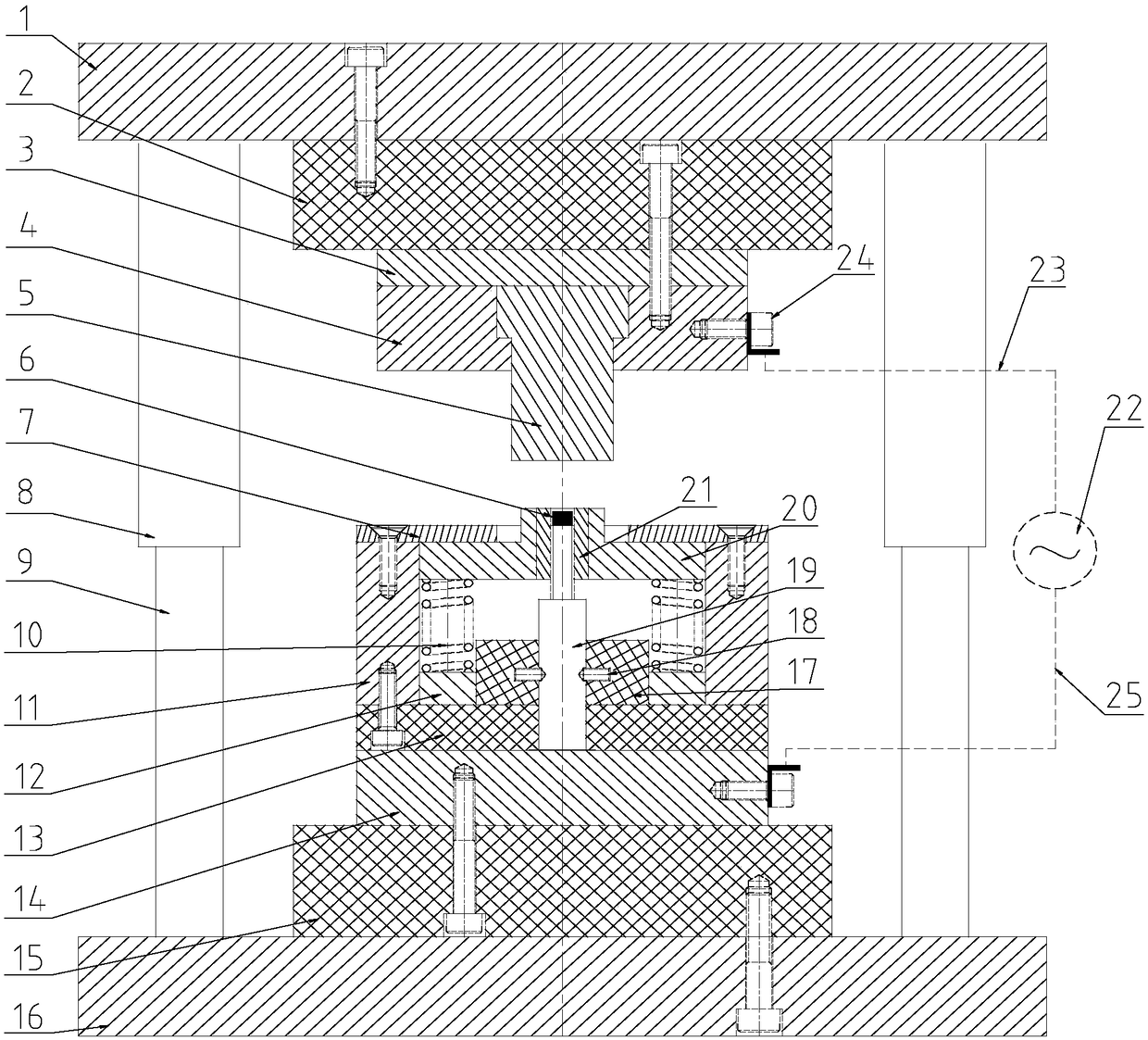
[0019] Specific implementation mode one: combine figure 1 To illustrate this embodiment, a titanium alloy micro-gear pulse current assisted micro-forming floating mold in this embodiment includes an upper die assembly, a lower die assembly, a punch 5, a punch 19, a die 21, a pulse power supply 22, The first wire 23, the second wire 25 and two wire joints 24, the upper mold assembly and the lower mold assembly are arranged in sequence from top to bottom, and the punch 5 is installed on the lower surface of the upper mold assembly , the punch 19 is installed on the upper surface of the lower mold assembly, the die 21 is set on the punch 19, and the inner wall of the die 21 and the upper end surface of the punch 19 form a cavity, and the cavity is located at the punch 5, the titanium alloy forging blank 6 is set in the cavity, one end of the first lead 23 is connected to the upper mold assembly through a lead joint 24, and the other end of the first lead 23 is connected to the pu...
specific Embodiment approach 2
[0022] Specific implementation mode two: combination figure 1 Describe this embodiment, the upper mold assembly of a titanium alloy micro-gear pulse current assisted micro-forming floating mold in this embodiment includes an upper template 1, an upper insulating plate 2, an upper backing plate 3 and a punch fixing plate 4, the upper Formwork 1, upper insulating plate 2, upper backing plate 3 and punch fixing plate 4 are stacked from top to bottom in sequence. Upper template 1 is detachably connected to upper insulating plate 2 through screws, and upper insulating plate 2 is connected to the impulse fixing plate through screws. 4 connection, one end of the first lead 23 is connected with the punch fixing plate 4 through a wire joint 24, and the upper end of the punch 5 is embedded in the middle part of the lower surface of the punch fixing plate 4. Other components and connections are the same as those in the first embodiment.
specific Embodiment approach 3
[0023] Specific implementation mode three: combination figure 1 Describe this embodiment, the lower mold assembly of a titanium alloy micro-gear pulse current assisted micro-forming floating mold in this embodiment includes a blank holder 7, a die fixing block 11, a spacer 12, and a first lower insulating plate 13 , the lower backing plate 14, the second lower insulating plate 15, the lower template 16, the insulating block 17, the pin 18, the sliding block 20 and two springs 10, the first lower insulating plate 13, the lower backing plate 14, the second lower insulating plate 15. The lower formwork 16 is stacked sequentially from top to bottom. The lower formwork 16 is detachably connected to the second lower insulating plate 15 through screws, and the second lower insulating plate 15 is detachably connected to the lower backing plate 14 through screws. The second wire 25 One end of the die is connected to the lower backing plate 14 through another wire joint 24, the lower en...
PUM
| Property | Measurement | Unit |
|---|---|---|
| diameter | aaaaa | aaaaa |
Abstract
Description
Claims
Application Information
 - Generate Ideas
- Intellectual Property
- Life Sciences
- Materials
- Tech Scout
- Unparalleled Data Quality
- Higher Quality Content
- 60% Fewer Hallucinations
Browse by: Latest US Patents, China's latest patents, Technical Efficacy Thesaurus, Application Domain, Technology Topic, Popular Technical Reports.
© 2025 PatSnap. All rights reserved.Legal|Privacy policy|Modern Slavery Act Transparency Statement|Sitemap|About US| Contact US: help@patsnap.com


