
An Additive Machining Forming Method for Complex Parts and Molds

A technology for complex parts, processing and forming, applied in the direction of additive processing, metal processing equipment, manufacturing tools, etc., can solve the problems of cumbersome process, and achieve the effect of wide applicability, good toughness and improved process stability

Active Publication Date: 2021-01-05
HUAZHONG UNIV OF SCI & TECH
View PDF8 Cites 0 Cited by
  • Summary
  • Abstract
  • Description
  • Claims
  • Application Information

AI Technical Summary

Problems solved by technology

[0005] In view of the above-mentioned shortcomings and / or improvement needs of the prior art, the present invention provides an additive processing forming method suitable for complex parts and molds, wherein according to the internal and external contour characteristics of the complex parts or the mold itself, a layered approach is adopted to gradually The precise processing of the inner and outer contours of the sheet is completed layer by layer, and it is especially able to perform stacking of each layer after the precise processing, and then position layer by layer, and finally complete the diffusion connection of each layer of sheet material in the form of overall diffusion connection, and the corresponding It can realize the processing and molding of parts and molds with complex internal and external contours, and can overcome the defects of poor process stability, mechanical performance decline and cumbersome process of the overall parts prepared by the existing forming process, and has high forming precision, high forming efficiency and low material cost. Low, high forming strength, good stability of forming process, etc.

Method used


Image

  • An Additive Machining Forming Method for Complex Parts and Molds
  • An Additive Machining Forming Method for Complex Parts and Molds
  • An Additive Machining Forming Method for Complex Parts and Molds

Examples


Embodiment 1

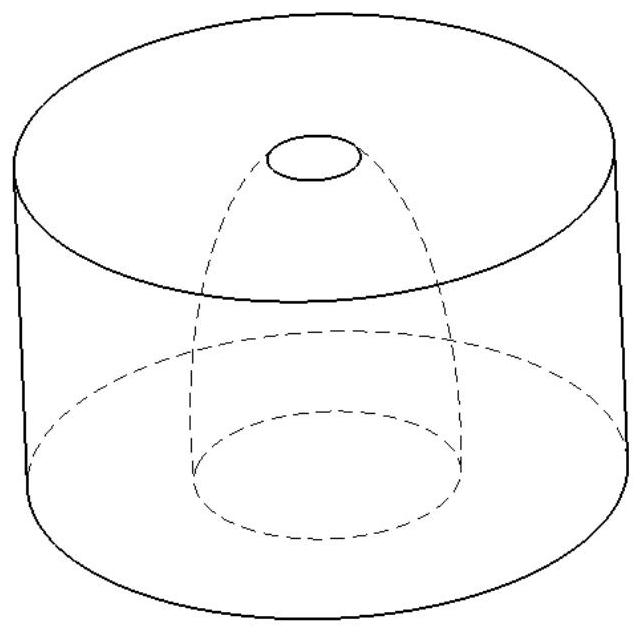
[0047] In this embodiment, the method of the present invention is further described by taking a metal part with a complex shape in the middle and two ends not closed as an example, which includes the following steps:

[0048] (1) Referring to Figure 1(a), the CAD geometric model of the part is established according to the three-dimensional shape and size of the target part, the STL model of the part is extracted, and the layer thickness is selected according to the actual shape and size of the part. In the actual operation process, the The layer thickness can be selected according to the actual needs. According to the shape and complexity of the part, the layer thickness of each layer can be the same or different, and the material can be the same or different. It is determined by the processing technology requirements of the part, and the operator can do it as needed. Reasonable selection and division, in the present embodiment, the layered thickness of each layer is selected t...

Embodiment 2

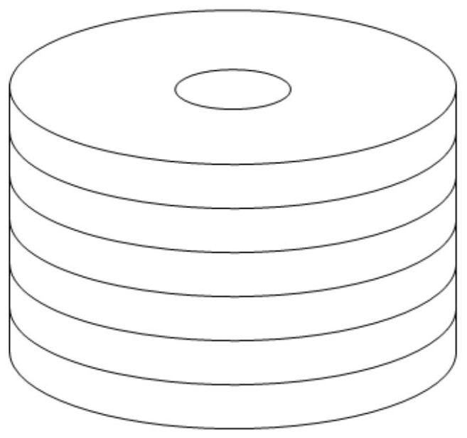
[0055] In this embodiment, the method of the present invention is further described by taking a metal mold with a complex shape and closed ends in the middle as an example, which includes the following steps:

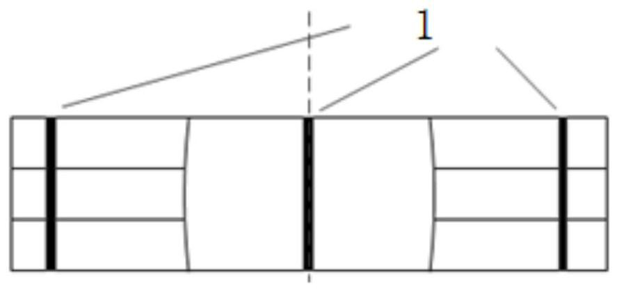
[0056] (1) Referring to Figure 2(a)-(b), the mold CAD geometric model is established according to the three-dimensional shape and size of the target mold, the STL model of the mold is extracted, and the layered thickness is selected according to the actual forming shape and size of the mold. During the process, the layer thickness can be selected according to the actual needs. According to the shape and complexity of the mold, the layer thickness of each layer can be the same or different, and the material can be the same or different, which is determined by the processing technology requirements of the mold. The operator Reasonable selection and division can be carried out according to needs, as shown in Figure 2 (c), the present embodiment is divided into blocks and th...


PUM

PropertyMeasurementUnit
thicknessaaaaaaaaaa
thicknessaaaaaaaaaa

Abstract

The invention discloses a method for additive processing and forming suitable for complex parts and molds, comprising the following steps: establishing a CAD geometric model of a part or a mold, extracting an STL model, and dividing the STL model into multiple layers with a preset layer thickness ; Separately extract the inner and outer contour points of multiple layers to form inner and outer contour trajectories, and generate numerical control instructions corresponding to each layer of processing based on the inner and outer contour trajectories; select the sheet material with the thickness of each layer as the processing object of each layer, and pass through the cutting device According to the CNC instructions corresponding to the processing of each layer, each layer of sheet material is cut; each layer is stacked according to the order of arrangement to obtain a blank or a blank, and each layer is accurately positioned during stacking, and then the The preforms are vacuum diffusion connected or the preforms are vacuum diffusion connected first, then stacked and finally vacuum diffusion connected. The invention has the advantages of high forming efficiency, high forming precision, low material cost, good forming stability and the like.

Description

technical field [0001] The invention belongs to the technical field of additive forming, and more specifically relates to an additive processing forming method suitable for complex parts and molds. Background technique [0002] Additive Manufacturing (AM, also known as 3D printing, rapid prototyping) technology originated in the late 1980s. Due to its unique principle and technological advantages, it has been verified from plastics, From the rapid prototyping technology of non-metallic prototypes such as paraffin and paper, to the rapid manufacturing technology of directly or indirectly preparing various molds, and then to the current rapid manufacturing technology of metal parts or molds, AM technology has achieved rapid development and practical application. The existing metal additive manufacturing methods mainly include fusion additive forming methods based on high-energy beams to melt powder and wire, and solid-state additive forming methods based on other energies. ...

Claims


Application Information

Patent Timeline
Patent Type & Authority Patents(China)
IPC IPC(8): B22F3/105B22F5/10B33Y10/00B23K28/02
CPCB22F5/007B22F5/10B23K28/02B33Y10/00B22F10/00B22F10/32B22F10/66B22F10/80Y02P10/25
Inventor 张海鸥谢龙龙王桂兰张华昱
Owner HUAZHONG UNIV OF SCI & TECH
Learn More