Eureka AIR delivers breakthrough ideas for toughest innovation challenges, trusted by R&D personnel around the world.

Vertical type pyrolysis device for solid organic waste

A technology of organic waste and pyrolysis, which is used in special forms of dry distillation, indirect heating dry distillation, petroleum industry, etc., can solve the problems of high sealing requirements of reactors, high pretreatment requirements, and unsuitable for industrial applications, so as to reduce heat Dissipated, reduced pyrolysis cost, and strong practicability

Active Publication Date: 2017-12-08
中海石油环保服务(天津)有限公司
View PDF8 Cites 12 Cited by
  • Summary
  • Abstract
  • Description
  • Claims
  • Application Information

AI Technical Summary

Problems solved by technology

The fixed bed mainly has two forms: a built-in screw propeller and a built-in agitator. In order to ensure thermal efficiency, both of them use a horizontal reactor, and the horizontal reactor occupies a relatively large area; the rotary kiln also uses a horizontal reactor. Type reactor, which occupies a large area. In addition, during the operation, the tightness of the reactor is required to be high, and the construction cost is high; the fluidized bed is a pyrolysis method with high heat transfer efficiency, but in the reaction process It needs gas as a medium to propel the material to form a fluidized state. It needs to use inert gas such as nitrogen as the fluidized gas source. However, it has high requirements for material pretreatment, complicated process operation, high operating costs, and a series of problems such as not being suitable for industrial applications.

Method used


Image

  • Vertical type pyrolysis device for solid organic waste
  • Vertical type pyrolysis device for solid organic waste
  • Vertical type pyrolysis device for solid organic waste

Examples


Embodiment 1

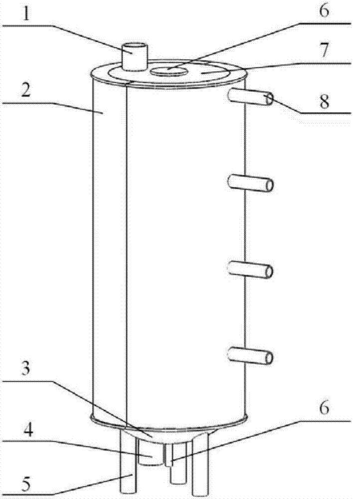
[0031] A vertical pyrolysis device for solid organic waste consists of a feed port 1, an insulation layer 2, a furnace bottom 3, a discharge port 4, a column 5, a transmission shaft 6, a furnace wall 7, a pyrolysis gas outlet 8, and a resistance sheet 9. Scraper 10, pallet 11, deflector 12, deflector canopy 13, bottom scraper 14 are formed. The feed port 1 is located above the tray 11; the resistor sheet 9 is placed between the insulation layer 2 and the furnace wall 7; the tray 11 is hollow and placed between the furnace walls 7, which can be welded or flanged; the middle of the deflector 12 is The shape of a triangular prism has three blades along the surface of the prism, which are fixed on the tray 11 and do not rotate with the transmission shaft 6; the scraper 10 is in the shape of a hook and rotates with the transmission shaft 6; The bottom surface is tangent; the deflector umbrella cover 13 is in the shape of an umbrella cover, connected to the transmission shaft 6, tan...


PUM


Abstract

The invention relates to a vertical type pyrolysis device for a solid organic waste, and belongs to the technical field of pyrolysis of organic matters. The vertical type pyrolysis device for the solid organic waste comprises a furnace wall, a thermal insulation layer, a transmission shaft, a resistor disc, scraping plates, trays, guide plates, guide canopies, a feed port, a discharge port and a pyrolysis gas outlet; the resistor disc is arranged on the inner wall of the thermal insulation layer of the furnace wall; the feed port is formed in the upper part; the scraping plates arranged in a layered manner are fixed on the transmission shaft and on the trays arranged in a layered manner; the guide plates are fixed on the inner sides of the trays; the guide canopies are arranged on the lower sides of the guide plates; the pyrolysis gas outlet is formed in the furnace wall; and a residue produced after the pyrolysis is discharged from the discharge port in the bottom part. The vertical type pyrolysis device for the solid organic waste adopts a vertical structure, has the advantages of small occupied area, and is suitable for the working place having high space requirements, the multi-stage shearing is adopted, the heat transfer rate is high, coking is not caused easily, the distribution of heat is even, the heat loss is low, and the pyrolysis cost is lowered.

Description

technical field [0001] The invention belongs to the technical field of pyrolysis of organic matter, in particular to a vertical pyrolysis device for solid organic waste. Background technique [0002] At present, the common furnace types for pyrolysis of organic solid waste mainly include fixed bed, rotary kiln, fluidized bed and other types. The main reactors of these furnace types have their own advantages in the pyrolysis process of solid organic waste, but there are also many problems. The fixed bed mainly has two forms: a built-in screw propeller and a built-in agitator. In order to ensure thermal efficiency, both of them use a horizontal reactor, and the horizontal reactor occupies a relatively large area; the rotary kiln also uses a horizontal reactor. Type reactor, which occupies a large area. In addition, during the operation, the tightness of the reactor is required to be high, and the construction cost is high; the fluidized bed is a pyrolysis method with high heat...

Claims


Application Information

Patent Timeline
Patent Type & Authority Applications(China)
IPC IPC(8): C10B53/00C10B47/36C10B47/20C10B43/14
CPCC10B43/14C10B47/20C10B47/36C10B53/00
Inventor 马蒸钊谢江浩刘涛王新新白鹤曹兴涛刘铭辉赵广宇郭兵杨庭谷广锋肖成磊
Owner 中海石油环保服务(天津)有限公司
Why Eureka
Eureka Blog
Learn More