
Thin film transistor substrate, display panel, and laser annealing method

A thin-film transistor and laser annealing technology, which is applied in transistors, laser welding equipment, electric solid-state devices, etc., can solve the problems of low electron mobility and the inability to fully cope with the high electron mobility of display panels

Inactive Publication Date: 2017-12-01
V TECH CO LTD
View PDF5 Cites 0 Cited by
  • Summary
  • Abstract
  • Description
  • Claims
  • Application Information

AI Technical Summary

Problems solved by technology

[0004] Although amorphous silicon TFT has good switching characteristics, there is "low electron mobility in the channel region, which is 0.5cm 2 / Vs” shortcoming, unable to fully cope with the high electron mobility required by higher density and high definition display panels in the future

Method used


Image

  • Thin film transistor substrate, display panel, and laser annealing method
  • Thin film transistor substrate, display panel, and laser annealing method
  • Thin film transistor substrate, display panel, and laser annealing method

Examples


Embodiment Construction

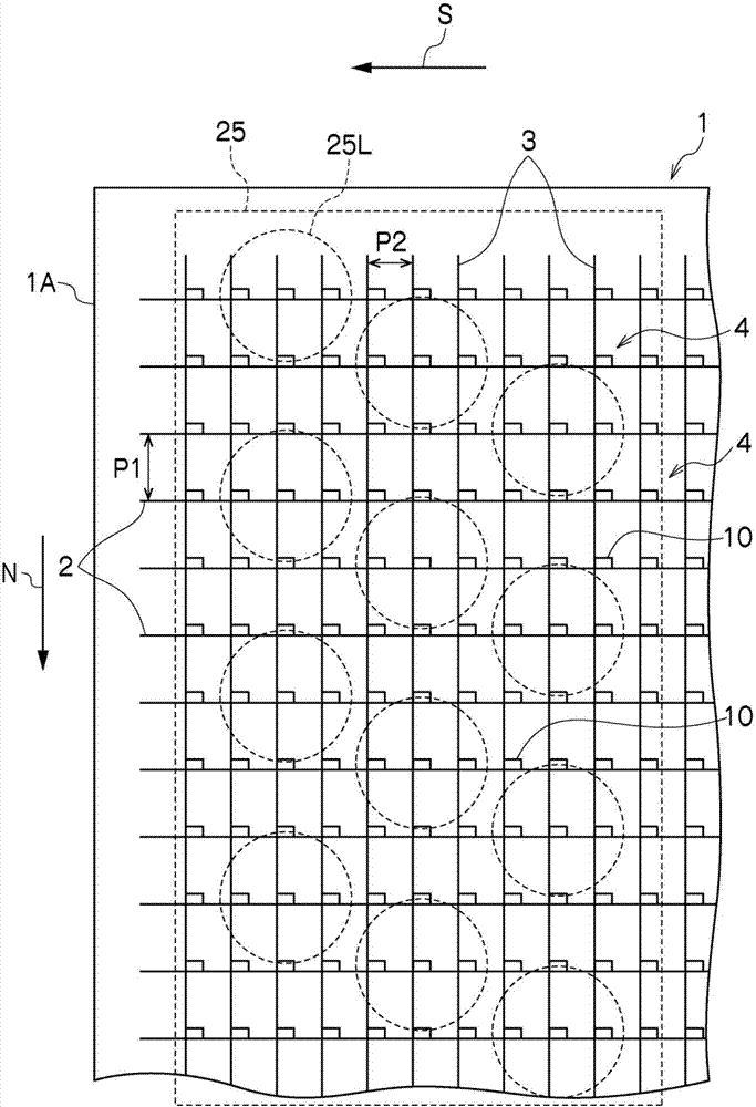
[0022] Hereinafter, embodiments of the present invention will be described with reference to the drawings. Such as figure 1 As shown, in the TFT substrate 1, a plurality of data lines 2 and gate lines 3 are respectively formed in columns and rows on the substrate, and TFTs 10 are formed near the intersections of the data lines 2 and gate lines 3, and each The TFT 10 is provided with a transparent electrode forming portion 4 . In this way, on the TFT substrate 1 , a plurality of TFTs 10 are arranged in columns and rows on the substrate 1A. In the illustrated example, the data lines 2 have a pitch of vertical width P1, and the gate lines 3 have a pitch of horizontal width P2. Correspondingly, the TFTs 10 have a pitch of vertical width P1 in columns and a pitch of horizontal width P2 in horizontal rows. arranged in a dot matrix.

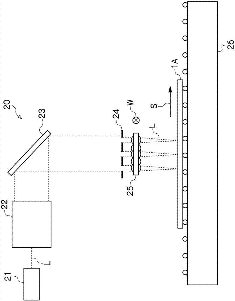
[0023] Laser annealing in the manufacture of TFT substrate 1, such as figure 1 As shown, the pattern of the gate line 3 is formed on the substrate ...


PUM


Abstract

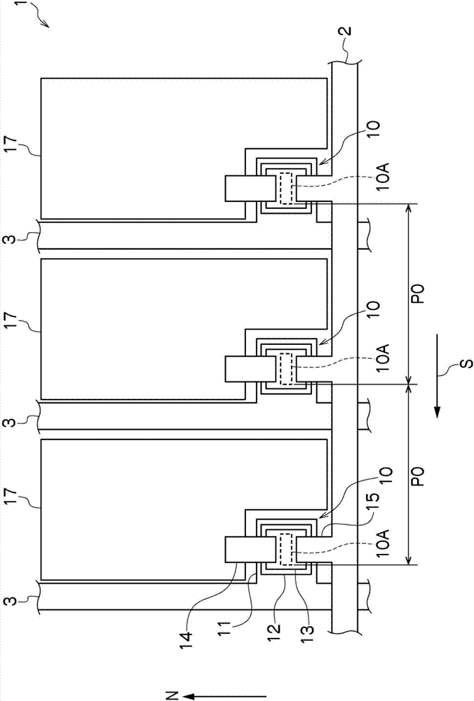
The invention discloses a thin film transistor substrate, a display panel, and a laser annealing method, aimed at obtaining a TFT substrate which has high charge mobility, high potential holding characteristics, and low power consumption, by improving throughput of laser annealing, and performing laser annealing by irradiating a laser beam pattern within a TFT channel width at a high accuracy. Disclosed is a thin film transistor substrate 1 wherein a plurality of thin film transistors 10 are disposed in columns and rows on a substrate 1A. The thin film transistors 10 are respectively provided with laser annealed sections 10A formed by laser annealing amorphous silicon layers 13 into polysilicon layers, said amorphous silicon layers forming channel regions, the laser annealed sections 10A are disposed at a set pitch in the scanning direction S in which the substrate and a laser beam for performing the laser annealing relatively move, and the thin film transistor substrate has each of the laser annealed sections 10 within a channel width W formed in the direction orthogonal to the scanning direction S, said each of the laser annealed sections having a width smaller than the channel width.

Description

technical field [0001] The invention relates to a thin film transistor substrate, a display panel provided with the thin film transistor substrate, and a laser annealing method for forming the thin film transistor substrate. Background technique [0002] As display panel substrates such as liquid crystal panels and organic EL panels of an active matrix driving method, generally known thin film transistor substrates are provided with thin film transistors (TFTs) arranged on each of a plurality of pixel electrodes arranged in a dot matrix. : thin film transistor). In particular, in the case of a display panel for color display, since RGB sub-pixels are aggregated into one pixel, a thin-film transistor is arranged for each sub-pixel that is three times the number of pixels on the thin-film transistor substrate. [0003] As thin film transistors (hereinafter referred to as TFTs), amorphous silicon TFTs excellent in switching characteristics have been used in recent years. Rega...

Claims


Application Information

Patent Timeline
Patent Type & Authority Applications(China)
IPC IPC(8): H01L21/20H01L21/268H01L21/336H01L29/786
CPCH01L21/268H01L29/66765H01L29/78618H01L29/78669H01L29/78678H01L27/1285H01L29/78696H01L21/324H01L29/786B23K26/066B23K26/0648H01L29/78663
Inventor 水村通伸
Owner V TECH CO LTD
Learn More