
Steam pipeline sealing device

A steam pipeline and sealing device technology, which is applied in the direction of pipes/pipe joints/fittings, flange connections, passing components, etc., can solve the problem of purchase cost, increased use cost, loose contact surface and valve clack, easy wear and tear Rust and other problems, achieve low density, enhance the sealing effect, overcome the effect of poor expansion resistance and impact resistance

Pending Publication Date: 2017-11-17
盐城润浩密封件科技有限公司
View PDF6 Cites 0 Cited by
  • Summary
  • Abstract
  • Description
  • Claims
  • Application Information

AI Technical Summary

Problems solved by technology

The gap between the valve disc and the valve body of the disc globe valve is large, and it is easy to wear and rust, so the sealing performance is poor, and frequent maintenance and replacement are required, resulting in increased purchase and use costs
In addition, in the existing steam pipeline sealing device, the contact surface between the valve body and the valve disc is usually set as a large plane, and the two hard planes are in contact with each other for sealing. Substances or impurities accumulate on this plane, resulting in a loose fit between the contact surface and the valve disc, which reduces the sealing performance. Another convenience is that due to the high temperature, high pressure and fast flow rate of the medium in the steam pipeline, it will give off during operation. The sealing gasket in the pipeline brings large expansion force and impact force, which makes the seal at the butt joint very easy to age, and it is inconvenient to replace it frequently. Therefore, we improve this and propose a steam pipeline sealing device

Method used


Image

  • Steam pipeline sealing device
  • Steam pipeline sealing device
  • Steam pipeline sealing device

Examples


Embodiment Construction

[0017] The following will clearly and completely describe the technical solutions in the embodiments of the present invention with reference to the accompanying drawings in the embodiments of the present invention. Obviously, the described embodiments are only some, not all, embodiments of the present invention. Based on the embodiments of the present invention, all other embodiments obtained by persons of ordinary skill in the art without making creative efforts belong to the protection scope of the present invention.

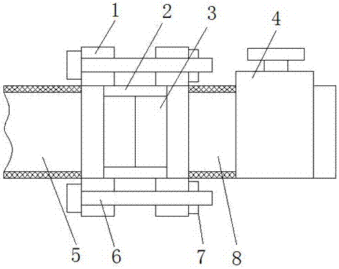
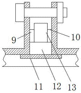
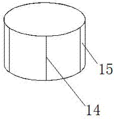
[0018] see Figure 1-3 , the present invention provides a technical solution: a steam pipe sealing device, including a flange 1, a gasket layer 3 and a high temperature resistant castable 9, the flange 1 is respectively arranged on the first steam pipe 5 and the second steam pipe At the port of the second steam pipe 8, a buffer interface 2 is provided between the first steam pipe 5 and the second steam pipe 8, and the first steam pipe 5 and the second steam pi...


PUM


Abstract

The invention discloses a steam pipeline sealing device comprising flange plates, a spacer layer and a high-temperature resistant castable. The flange plates are arranged at ports of a first steam pipeline and a second steam pipeline; a buffer connector is arranged between the first steam pipeline and the second steam pipeline, and the first steam pipeline and the second steam pipeline are fixed to the two sides of an annular groove correspondingly; a bump is connected to the outer side of the annular groove; a groove is formed in the periphery of the bump and filled with the high-temperature resistant castable; and a fixed piece is arranged on the inner side of the annular groove; and the spacer layer is arranged on the inner wall of the fixed piece. The spacer layer is arranged, thus the adhesive force of a graphite gasket in the sealing process is increased through a polyethylene plate; and the polyethylene plate is good in heat resistance, cold resistance and chemical stability and high in mechanical strength, so that the sealing effect of the butt joint position of the flange plates of the steam pipelines is strengthened, accordingly the steam pipeline sealing device can be used in a high temperature state for a long time and meanwhile is easy to replace, detach and mount.

Description

technical field [0001] The invention relates to the technical field of pipeline sealing equipment, in particular to a steam pipeline sealing device. Background technique [0002] The sealing technology of the on-off control part of the steam system pipeline is an urgent problem to be solved in the relevant field at present. The traditional control method generally adopts the disc globe valve. The gap between the valve disc and the valve body of the disc globe valve is large, and it is easy to wear and rust, so the sealing performance is poor, and frequent maintenance and replacement are required, resulting in increased purchase and use costs. In addition, in the existing steam pipeline sealing device, the contact surface between the valve body and the valve disc is usually set as a large plane, and the two hard planes are in contact with each other for sealing. Substances or impurities accumulate on this plane, resulting in a loose fit between the contact surface and the va...

Claims


Application Information

Patent Timeline
Patent Type & Authority Applications(China)
IPC IPC(8): F16L23/16
CPCF16L23/162
Inventor 黄海进
Owner 盐城润浩密封件科技有限公司
Learn More