
Ammonia gas automatic-supplying method of solid ammonia system heated by using engine waste heat

A heating method and engine technology, applied in engine components, combustion engines, machines/engines, etc., can solve problems such as the inability to meet large endurance, and achieve the effect of simple and easy heating solution, time saving, and improved continuation ability.

Pending Publication Date: 2017-11-03
CHINA FIRST AUTOMOBILE
View PDF9 Cites 6 Cited by
  • Summary
  • Abstract
  • Description
  • Claims
  • Application Information

AI Technical Summary

Problems solved by technology

[0005] The current diesel vehicles are used by users to pursue greater battery life, so the OEM has increased the fuel tank volume to 800L. The current vehicle-mounted reducing agent has certain limitations in the battery life and cannot meet the needs of large battery life. Therefore The on-board ammonia source needs to be replenished

Method used


Image

  • Ammonia gas automatic-supplying method of solid ammonia system heated by using engine waste heat
  • Ammonia gas automatic-supplying method of solid ammonia system heated by using engine waste heat

Examples


Embodiment 1

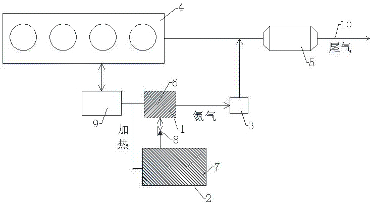
[0036] Use the exhaust gas of the engine to heat the main container 1 of the ammonia storage material, the exhaust temperature is usually between 150°C and 350°C, and the exhaust gas flow into the ammonia storage material container is controlled through one of the heating units 9—the exhaust gas three-way valve , heat the ammonia storage material 6 in the main container to desorb and release ammonia gas; control the pressure P1 in the main container 1 of the ammonia storage material to reach the working pressure between 1.2 and 3 bar; when P1 is greater than 1.2 bar, the reducing agent metering control unit DCU 3 according to the pressure The ammonia pressure value in the container detected by the sensor, after confirming that the state satisfies the working conditions, calculates the amount of ammonia gas required for emission treatment of NOx according to the engine operating parameters (speed, fuel consumption, etc.) transmitted by the engine ECU, and performs metered injecti...

Embodiment 2

[0042] Use the exhaust gas of the engine to heat the main container 1 of the ammonia storage material. The exhaust temperature is usually between 150°C and 350°C. The exhaust gas three-way valve is controlled by the heating unit 9 to control the flow of the exhaust gas into the ammonia storage material container, and the main heating The ammonia storage material 6 in the container desorbs and releases ammonia gas; the pressure P1 in the main container 1 of the ammonia storage material is controlled to reach the working pressure between 1.2 and 3 bar; when P1 is greater than 1.2 bar, the reducing agent metering control unit DCU3 The ammonia pressure value in the container, after confirming that the state meets the working conditions, calculates the amount of ammonia gas required to meet the emission and treatment of NOx according to the engine operating parameters (speed, fuel consumption, etc.) transmitted by the engine ECU, and injects the ammonia gas in a metered manner. The ...

Embodiment 3

[0047] like Figure 1-2 As shown, the ammonia storage material main container heating unit 9 uses a vehicle-mounted power supply electric heater to heat the ammonia storage material main container 1. When the heating temperature is higher than 50°C, the material in the ammonia storage material main container 1 begins to desorb after being heated. Release ammonia gas; the heating power is selected according to the size of the container, the power is between 200W~1000, and the heating temperature is controlled within 200°C, so that the ammonia storage material 6 in the main container of the ammonia storage material main container 1 releases ammonia gas quickly, and the ammonia gas in the container The pressure P1 reaches the controlled working pressure between 1.2 and 3bar; when P1 is greater than 1.2bar, the reducing agent metering control unit DCU3 confirms that the state meets the working conditions according to the ammonia pressure value in the container detected by the press...


PUM


Abstract

The invention relates to an ammonia gas automatic-supplying method of a solid ammonia system heated by using engine waste heat. The ammonia gas automatic-supplying method of the solid ammonia system heated by using the engine waste heat is characterized in that heating is conducted on an ammonia storage material main container and an ammonia storage material supplying container through a heating unit, when reaching a desorption temperature, ammonia materials in the main container release ammonia gas; and a pressure P1 in the ammonia storage material main container reaches a working pressure, a reducing-agent metering control unit DCU conducts metering on the ammonia gas, and the jet quantity of the ammonia gas is metered according to engine operating parameters (rotate speed, fuel consumption and the like) transmitted by an engine ECU. The ammonia gas is jetted into an exhaust pipe from the front end of an SCR catalytic converter, the ammonia gas and engine exhaust gas are mixed sufficiently, and under the effect of a catalyzer, NOx is decontaminated into harmless water and a nitrogen gas; and by utilizing the principle of the pressure difference formed between the pressure P1 in the ammonia storage material main container and a pressure P2 in the ammonia storage material supplying container, the ammonia gas automatic-supplying system convenient to achieve is designed; and the problem that the cruising capacity of an existing vehicle-mounted ammonia source is low is solved, and the ammonia gas automatic-supplying method of the solid ammonia system heated by using the engine waste heat is ingenious in idea, convenient to implement, high in reliability and good in economic efficiency.

Description

technical field [0001] The invention relates to an automatic ammonia supply method for a solid ammonia system in an engine waste heat heating mode, uses a reducing agent material that can absorb and desorb ammonia gas based on a solid form, and is applied in the technical field of catalytic purification of nitrogen oxides in motor vehicle tail gas. Background technique [0002] The use of selective catalytic reduction (SCR) technology to treat NOx in motor vehicle exhaust is currently the mainstream technology for diesel vehicles. The use of reducing agent materials that can absorb and desorb ammonia to release ammonia is a technical upgrade of the urea aqueous solution reducing agent. . Utilizing the characteristic of forming coordination compounds between metal chlorides and ammonia gas, ammonia gas is fixed. The metal chlorides used are mainly alkaline earth metal chlorides, strontium chloride, calcium chloride, magnesium chloride, and necessary auxiliary components. . ...

Claims


Application Information

Patent Timeline
Patent Type & Authority Applications(China)
IPC IPC(8): F01N3/20F02G5/04
CPCF01N3/2066F02G5/04F01N2610/12F01N2610/10F01N2610/02Y02A50/20Y02T10/12
Inventor 崔龙张克金韩建于力娜苏中辉郑晓旭
Owner CHINA FIRST AUTOMOBILE
Learn More