
Assembly method for end covers of gas-liquid separator or oil-gas separator

An assembly method and end cap technology, which are applied to resistance welding equipment, arc welding equipment, manufacturing tools, etc., can solve the problems of low positioning accuracy, inconvenient fixing of brackets, and long welding time, so as to simplify the processing process, and to move left and right. Difficulty, good yielding effect

Active Publication Date: 2017-09-12
WUHU SANHUA REFRIGERATION FITTINGS
View PDF11 Cites 1 Cited by
  • Summary
  • Abstract
  • Description
  • Claims
  • Application Information

AI Technical Summary

Problems solved by technology

[0006] Both of the above two brackets can realize the fixing of the gas-liquid separator and the air conditioner, but they still have not solved the problems of inconvenient fixing of the bracket, difficulty in assembly, high scrap rate, long welding time, and low positioning accuracy in the prior art, and need to be improved.

Method used


Image

  • Assembly method for end covers of gas-liquid separator or oil-gas separator
  • Assembly method for end covers of gas-liquid separator or oil-gas separator
  • Assembly method for end covers of gas-liquid separator or oil-gas separator

Examples


Embodiment 1

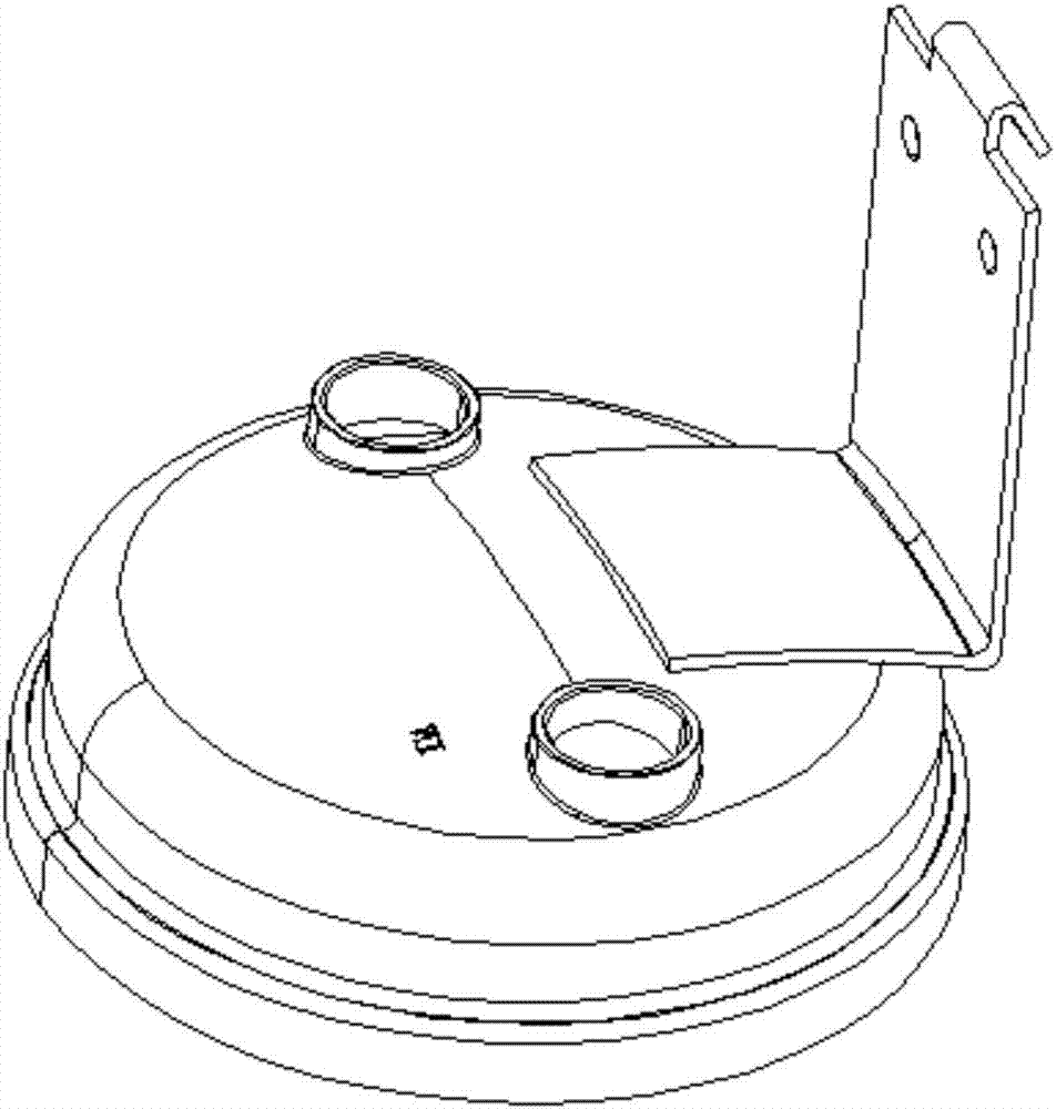
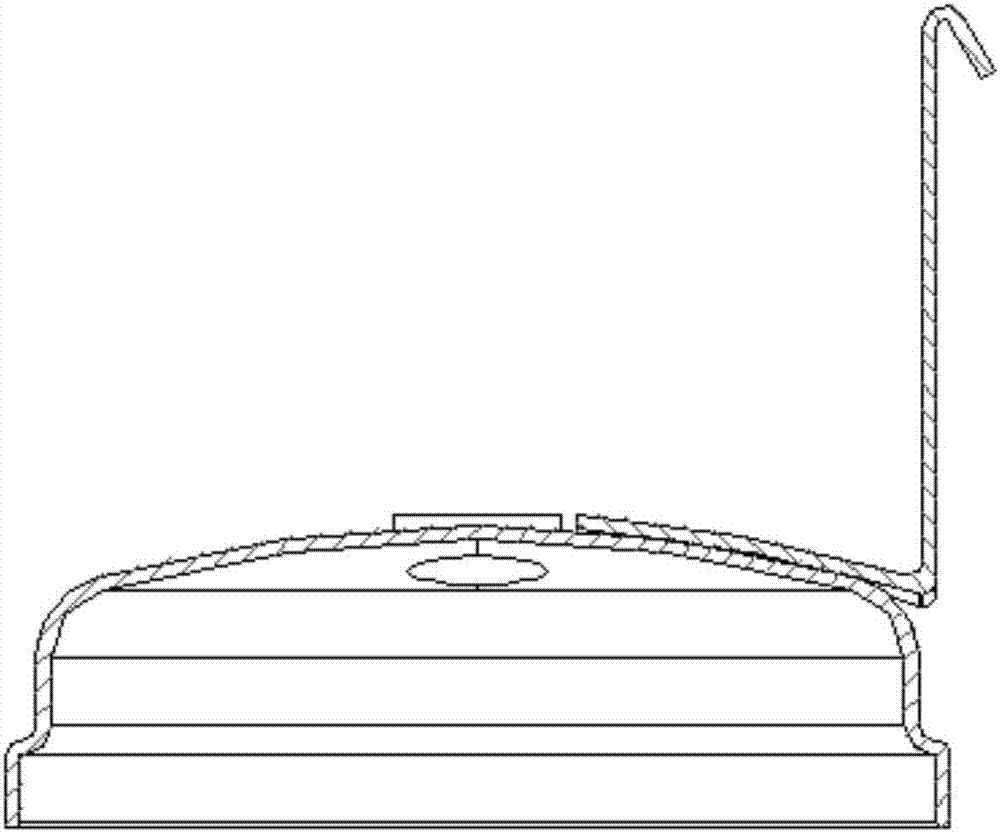
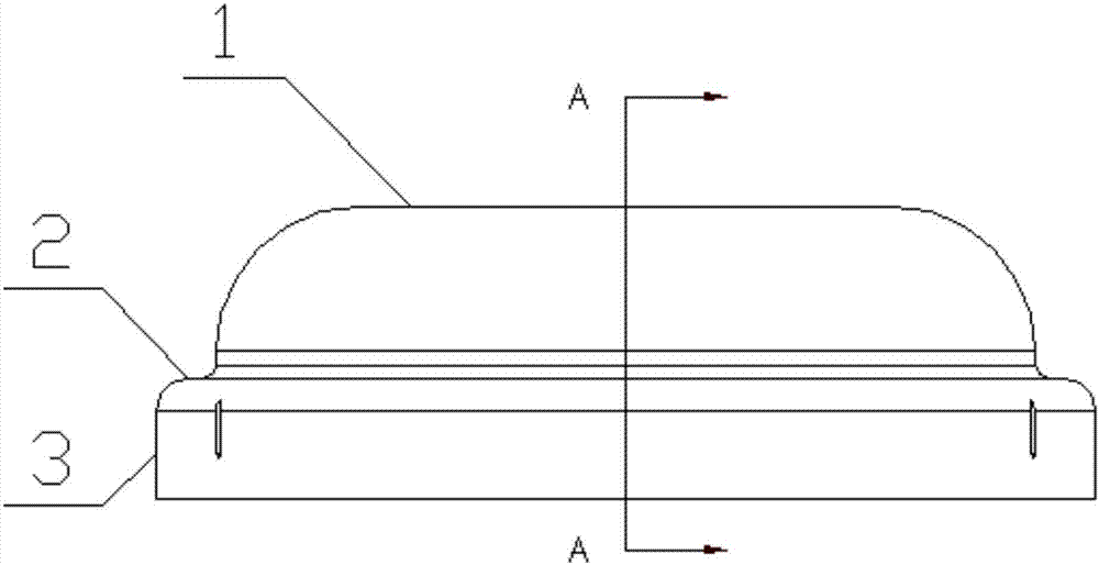
[0043] like Figure 2 to Figure 7 As shown, an end cap for gas separation and oil separation includes a cover body, and the cross section of the cover body sequentially includes a vertical section 3, a horizontal shoulder 2 and at least one plane section 1 from bottom to top. The surface section 3 forms a tubular structure, and the horizontal shoulder 2 and the vertical surface section 3 are perpendicular to each other, and their connection adopts a circular arc transition. The final shape of the device needs to be completed through multiple stamping processes.

[0044] like Figure 4 As shown, the L plane is CO 2 Welding positioning datum plane, M plane is resistance welding positioning datum plane and press fit height guarantee plane, N plane is CO 2 Weld height reference plane.

[0045] In this embodiment, the top of the cover body is a plane segment 1 as a whole, and its shape is specifically circular, and an outwardly protruding arc-shaped curved surface is used betwe...

Embodiment 2

[0052] like Figure 10 to Figure 15 As shown, an end cap for gas separation and oil separation includes a cover body, and the cross section of the cover body sequentially includes a vertical section 3, a horizontal shoulder 2 and at least one plane section 1 from bottom to top. The surface section 3 forms a tubular structure, and the horizontal shoulder 2 and the vertical surface section 3 are perpendicular to each other, and their connection adopts a circular arc transition. The final shape of the device needs to be completed through multiple stamping processes.

[0053] In this embodiment, the top of the cover body as a whole is a plane section 1 and its shape is specifically a quincunx shape. The top of the cover body can be provided with anti-stretch holes-10 as required, such as Figure 4 shown.

[0054] In this embodiment, the inner wall of the vertical surface section 3 is provided with a number of circumferentially arranged inner ribs 5, on the one hand for ensuring...


PUM

PropertyMeasurementUnit
heightaaaaaaaaaa

Abstract

The invention discloses an assembly method for end covers of a gas-liquid separator or oil-gas separator, and relates to the technical field of air conditioner part assembly. The assembly method comprises the following steps: one of the end covers is connected with brackets by adopting electric resistance welding, the end cover is fixed with a device body in a welding manner by adopting CO2 protective welding, and finally the other end cover is welded at the other end of the device body by adopting the same method, so as to complete the disassembly of the end covers and refrigeration equipment. According to the assembly method for the end covers of the gas-liquid separator or oil-gas separator, the fixation between the end covers and the brackets is convenient, the assembly difficulty is reduced, the rejection rate is low, the welding time is short, and the positioning precision is high.

Description

technical field [0001] The invention relates to the technical field of assembly of air-conditioning accessories, in particular to an assembly method of an end cover for gas separation and oil separation. Background technique [0002] The refrigeration system usually consists of 4 basic parts, namely compressor, condenser, throttling parts and evaporator. The four parts are connected in a certain order by copper tubes to form a closed system, and a certain amount of refrigerant is filled in the system. The general air-conditioning refrigerant is Freon, and R22 is usually used in the past, and now some air-conditioning Freon has adopted a new type of environmentally friendly refrigerant R407. [0003] Gas-liquid separators are widely used in refrigeration equipment. Gas-liquid separators are used in COOT (orifice and tube) air-conditioning systems. superior. Existing gas-liquid separators are generally fixed in the air conditioner through brackets or brackets. In the curren...

Claims


Application Information

Patent Timeline
Patent Type & Authority Applications(China)
IPC IPC(8): B23K31/02B23K11/00B23K9/16B23P19/02
CPCB23K9/16B23K11/002B23K31/02B23P19/02
Inventor 郭晓明
Owner WUHU SANHUA REFRIGERATION FITTINGS
Learn More