
Disk spring set for shock insulation support

A technology of disc springs and shock-isolation bearings, which is applied in the direction of shock resistance, building components, building types, etc., can solve the problems of disc springs being unable to deform, disc springs with poor shock-isolation effects, and loss of shock-isolation effects. Achieve the effect of simple and effective stiffness adjustable and good welding fixation

Active Publication Date: 2019-04-12
中震华创(深圳)技术有限公司
View PDF5 Cites 1 Cited by
  • Summary
  • Abstract
  • Description
  • Claims
  • Application Information

AI Technical Summary

Problems solved by technology

Therefore, the difficulty in the vertical seismic isolation (vibration) design of buildings lies in how to provide effective vertical support for the superstructure at the same time, increase the vertical period of the structure after isolation (vibration) with high strength, and avoid overturning of the superstructure at the same time. Therefore, the prior art provides a vertical vibration isolation bearing with friction damping, which enhances the vertical vibration isolation of the vibration isolation bearing by arranging a disc spring group and a friction damping structure. effect, however, the stiffness of the existing disc spring group is fixed, and the vibration frequency and amplitude are changed during the operation of the subway, and the vibration isolation process of the above-mentioned vibration isolation bearing is mainly The corresponding vibration energy is absorbed by the deformation of the disc spring group, so if the vibration intensity is small, it is easy to cause the disc spring to fail to deform, so that the upper and lower connecting plates become a rigid connection, and then lose The corresponding shock isolation effect, or when the vibration intensity is high, the disk spring cannot effectively absorb the vibration energy due to insufficient stiffness, resulting in poor shock isolation effect

Method used


Image

  • Disk spring set for shock insulation support
  • Disk spring set for shock insulation support
  • Disk spring set for shock insulation support

Examples


specific Embodiment approach

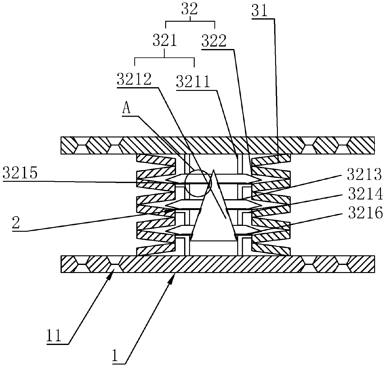
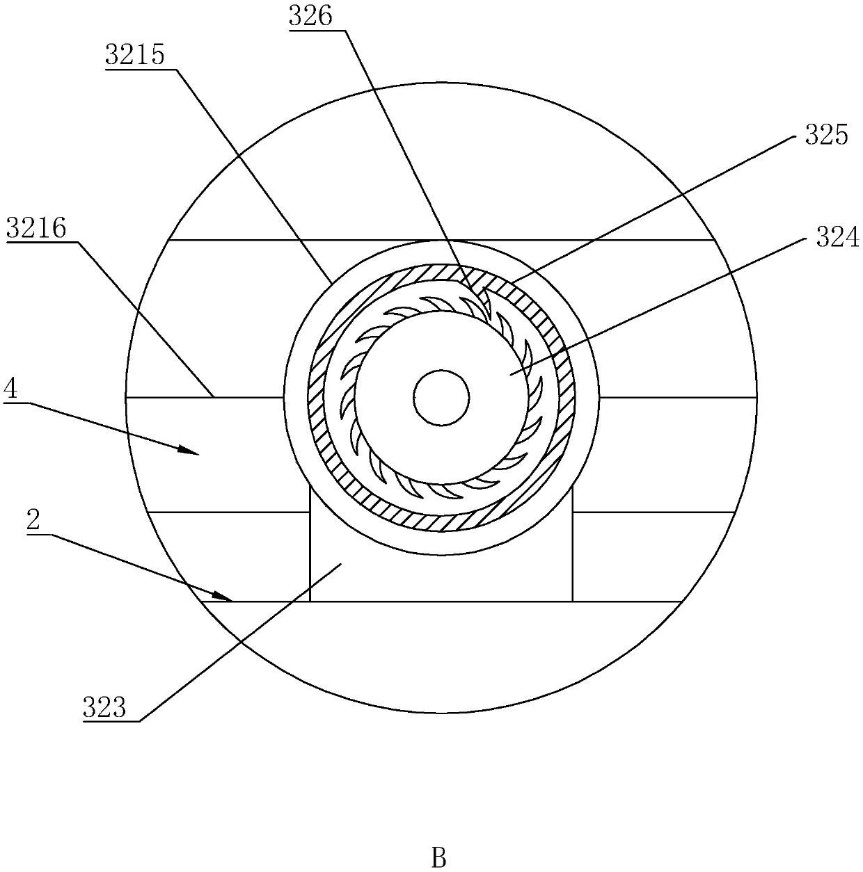
[0017]As an improved specific implementation, the vibration detection assembly 321 includes a column housing 3211 and a detection column 3212. The column housing 3211 is hollow and expandable, and its two ends are respectively fixed to the upper connecting plate 1 and the lower connecting plate 2. Connected, coaxially arranged in the disc spring 31, the detection column 3212 is slidably arranged in the column housing 3211, and the position of the side wall of the column housing 3211 relative to the interlayer of the disc spring 31 corresponds one by one There is a drive hole 3213 for the elastic block 322 to pass through, and the elastic block 322 is passed through the drive hole 3213, and is linked with the side wall of the detection column 3212, when the detection column 3212 slides up and down in the column housing 3211 , the detection column 3212 pushes the elastic block 322 to slide into the interlayer of the disc spring 31, or slides out from the interlayer. When the lowe...


PUM


Abstract

The invention discloses a disk spring set for a shock insulation support. The disk spring set comprises a disk spring and a rigidity adjusting mechanism arranged in the disk spring, two ends of the disk spring are fixedly connected with an external upper connecting plate and an external lower connecting plate respectively; and the section of the disk spring is of a corrugated pipe structure; the rigidity adjusting mechanism comprises a vibration detection assembly and an elastic block slidably embedded in an interlayer of the disk spring, the elastic block is in linkage with the vibration detection assembly, fixing plates are arranged at two ends of the disk spring, a plurality of welding holes are formed in a fixing plate, and the welding holes penetrate through two faces of the fixing plate. According to the disk spring set for the shock insulation support, through the arrangement of the rigidity adjusting mechanism, the rigidity of the disk spring set can be effectively adjusted, and therefore the problem that shock insulation cannot be achieved due to the fact that the disk spring set is too high in rigidity to deform in the prior art is solved.

Description

technical field [0001] The present invention relates to a disc spring group, in particular to a disc spring group for shock-isolation bearings. Background technique [0002] Earthquake disasters bring immeasurable loss of life and property to human beings. The base isolation (vibration) system is to install some kind of isolation and energy dissipation device between the upper structure and the foundation to reduce the transmission of seismic (vibration) energy to the upper part and achieve the purpose of reducing structural vibration. [0003] The research on the horizontal isolation technology of building foundations has achieved remarkable results, and has been widely used in engineering practice. However, there are relatively few researches on isolation (vibration) of environmental vibration induced by subway operation and vertical vibration caused by vertical earthquake. In actual engineering, it is difficult to significantly reduce the vertical stiffness if the seism...

Claims


Application Information

Patent Timeline
Patent Type & Authority Applications(China)
IPC IPC(8): E04B1/98E04H9/02
CPCE04H9/021
Inventor 黄剑涛肖华宁宋廷苏
Owner 中震华创(深圳)技术有限公司
Learn More