
Method for Chassis Control of a Motor Vehicle, and Device for the Performance Thereof

Active Publication Date: 2012-03-08
ROBERT BOSCH GMBH
View PDF15 Cites 32 Cited by
  • Summary
  • Abstract
  • Description
  • Claims
  • Application Information

AI Technical Summary

Benefits of technology

[0011]Upon initiation of cornering by changing the steering wheel angle, the first valve of at least one shock absorber on the outside of the curve and the second valve of at least one shock absorber on the inside of the curve are advantageously switched to increase the stiffness. In this case, a vehicle-side-dependent activation of the shock absorbers therefore occurs, while in contrast an axle-dependent activation is performed during the brake application. During the occurring cornering, i.e., when a rolling movement of the vehicle body occurs, the second valve of the at least one shock absorber on the outside of the curve and the first valve of the at least one shock absorber on the inside of the curve are switched to increase the stiffness. In other words, upon initiation of cornering, a compressive load of the shock absorber on the outside of the curve is expected and the first valve is therefore switched to increase the stiffness of the compression stage, while the stiffness of the rebound stage of the shock absorber on the inside of the curve, where the shock absorber experiences a tensile load, is switched to increase the stiffness. Before the vehicle body swings back or the vehicle body return movement occurs, the remaining stages of the shock absorbers are also switched to increase the stiffness. The rolling movement of the vehicle body during cornering is thus minimized and the driving comfort is increased.

Problems solved by technology

Thus, roadway roughness may also excite global vehicle body movements, and driving interventions of the driver may result in local movements of the shock absorber.
Recognition using body movement sensors and reaction time due to signal transmission and processing would be too slow for this purpose.

Method used


Image

  • Method for Chassis Control of a Motor Vehicle, and Device for the Performance Thereof
  • Method for Chassis Control of a Motor Vehicle, and Device for the Performance Thereof
  • Method for Chassis Control of a Motor Vehicle, and Device for the Performance Thereof

Examples


Embodiment Construction

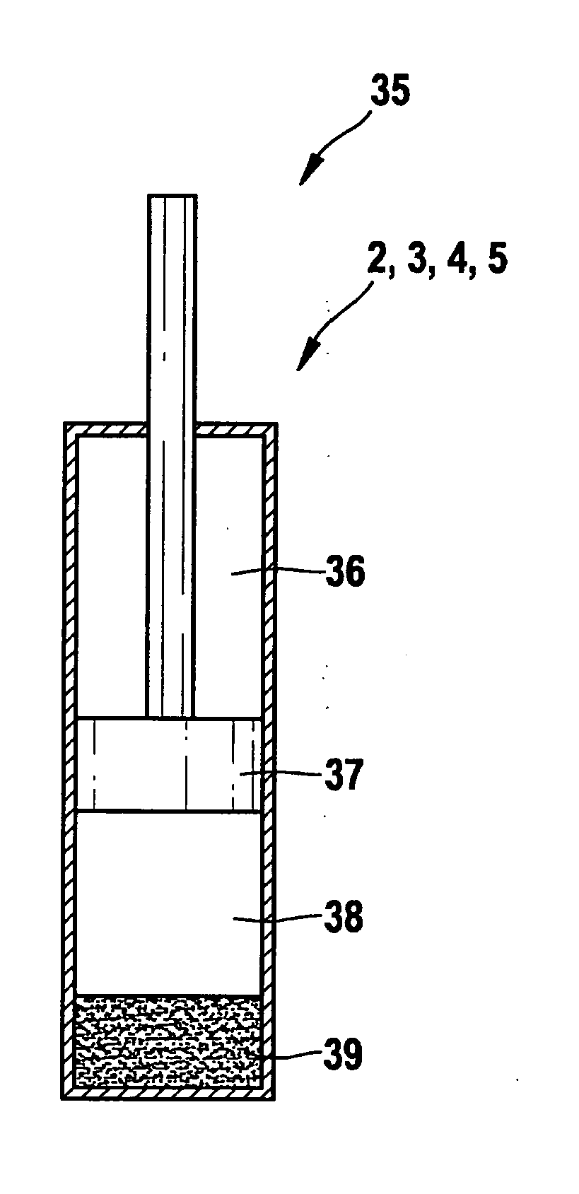
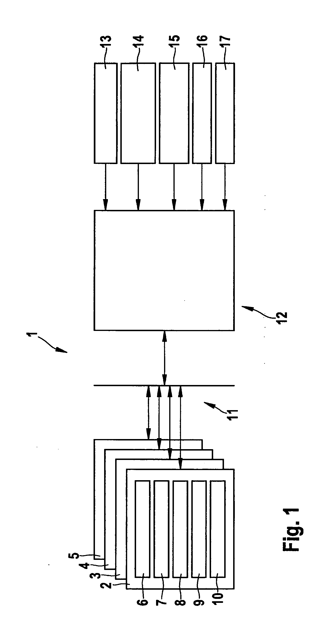
[0037]FIG. 1 shows a system structure 1, as may be used in the method according to the present invention and / or the device according to the present invention, for example. Four shock absorbers 2, 3, 4, and 5 are provided, each shock absorber being associated with one wheel of a motor vehicle (not shown). Shock absorbers 2, 3, 4, and 5 are provided between the wheel and a body of the motor vehicle, i.e., they are a component of a wheel suspension (also not shown). Each adjustable shock absorber has pressure sensors 6, a microprocessor 7, two output stages 8, with the aid of which a valve drive 9 may be activated in each case, and, via the valve drive, a valve 10. Each of pressure sensors 6, output stages 8, valve drives 9, and valves 10 are associated with one rebound stage and one compression stage of shock absorber 2 in each case. Therefore, one of pressure sensors 6 is used for the purpose of determining the pressure in the compression stage, while the other of pressure sensors 6 ...


PUM


Abstract

In a method for chassis control of a motor vehicle which has at least one wheel suspension, a vehicle body, and a shock absorber having a rebound stage, whose stiffness is adjustable, and a compression stage, whose stiffness is adjustable, the stiffness of the compression stage is changed for a compressive load of the shock absorber generated by a specific vehicle body movement, and the stiffness of the rebound stage is additionally changed for a subsequently following tensile load of the shock absorber generated by the specific vehicle body movement, or the stiffness of the rebound stage is changed for a tensile load of the shock absorber generated by a specific vehicle body movement, and the stiffness of the compression stage is additionally changed for a subsequently following compressive load of the shock absorber generated by the specific vehicle body movement.

Description

BACKGROUND OF THE INVENTION[0001]1. Field of the Invention[0002]The present invention relates to a device and a method for chassis control of a motor vehicle, which has at least one wheel suspension, which carries a vehicle body, having a shock absorber.[0003]2. Description of Related Art[0004]Methods for chassis control of a motor vehicle are known from the related art. For example, a method for activating a shock absorber, which is adjustable in its damping characteristic, of a motor vehicle is known from published German patent application document DE 41 120 04 C2. For this purpose, the shock absorber has an adjustable valve for adjusting the damping characteristic, the changeovers between the damping characteristics to be performed to optimize the properties of the motor vehicle being a function of whether the shock absorber is loaded by compression or tension. The stiffness of the shock absorber, i.e., the damping ratio, is set in such a way that the movement of the vehicle bod...

Claims


Application Information

Patent Timeline
IPC IPC(8): B60G17/0165B60G17/08F16F9/50
CPCB60G17/0161B60G2800/22B60G17/018B60G17/08B60G2400/0521B60G2400/0522B60G2400/102B60G2400/204B60G2400/252B60G2400/39B60G2400/41B60G2400/5182B60G2500/10B60G2600/184B60G2600/187B60G2600/604B60G2800/012B60G2800/014B60G2800/164B60G17/0162
Inventor BUETTNER, SILKEDURDEVIC, IVICABOEKER, RALPHSANKIN, ROMANHABENICHT, ALEXANDERKNOOP, MICHAELWAGNER, OLIVER
Owner ROBERT BOSCH GMBH
Learn More