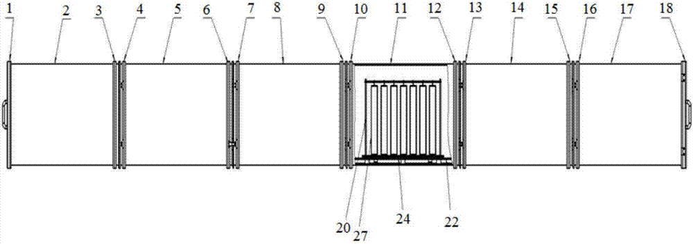
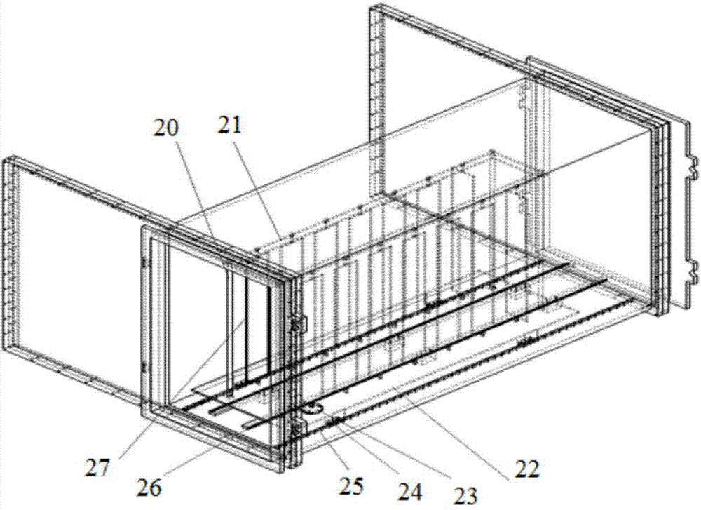
Fuel cell metal polar plate vacuum coating flow-line equipment and coating method thereof
A metal plate and fuel cell technology, applied in vacuum evaporation coating, metal material coating process, sputtering coating, etc., can solve the problems of small furnace loading, single exhaust system, low production efficiency, etc.
- Summary
- Abstract
- Description
- Claims
- Application Information
AI Technical Summary
Problems solved by technology
Method used
Image
Examples
Embodiment 1
[0087] The second coating room is equipped with three pairs of graphite targets. Along the direction of the turret, the cathode of the first pair of graphite targets is a closed field unbalanced field magnetron target, a rectangular planar magnetron target, followed by an ion source, and the second pair of graphite targets. The target is a graphite target with a balanced magnetic field rectangular planar magnetron target, and the third pair of graphite targets is a closed-field unbalanced magnetron target, and the unbalanced methods are all relative to the target structure. This layout method is based on the following considerations:
[0088] There are certain differences in the films prepared by sputtering with balanced magnetron sputtering targets and sputtering with unbalanced magnetron sputtering targets. This arrangement can form a hard-soft-hard coating system alternately. It is beneficial to avoid the failure phenomenon of the anti-corrosion conductive coating due to ex...
Embodiment 2
[0099] The second coating room is equipped with three pairs of graphite targets. Along the direction of the turret, the cathode of the first pair of graphite targets is a closed-field unbalanced field rectangular planar magnetron graphite target, followed by an ion source, and the second pair of graphite targets is a balanced Magnetic field rectangular planar magnetron target graphite target, followed by the third pair of targets is balanced magnetic field rectangular planar magnetron target niobium target, the fourth pair of targets is unbalanced field rectangular planar magnetron target rectangular planar magnetron graphite target. This target layout method is based on the following considerations:
[0100] Doping Nb in the amorphous carbon coating is beneficial to improve the corrosion resistance of the metal plate of the fuel cell. In addition, the doping of Nb can also avoid the increase of the contact resistance of the amorphous carbon coating during service.
[0101] Un...
Embodiment 3
[0111] The second coating chamber is equipped with three pairs of Au targets, and the cathodes of the three pairs of Au targets are all closed-field unbalanced-field rectangular planar magnetron targets. An Au recovery device is arranged on the wall of the second coating chamber. Considering the characteristics of this process, the ion source device was not used.
[0112] Under the premise of this target layout pattern, the process preparation method is as follows:
[0113] 1) Preparatory work, including stamping metal plates, single plate welding, cleaning and other steps. The cleaning process of the metal plate is alkali washing-deionized water ultrasonic cleaning-acid washing-deionized water ultrasonic cleaning-deionized water ultrasonic cleaning-alcohol ultrasonic-drying;
[0114] 2) Furnace loading in the furnace chamber. In order to ensure the vacuum degree of the furnace chamber, the furnace loading method adopted in the present invention is as follows: in the clean r...
PUM
 Abstract
Description
Claims
Application Information
 - Generate Ideas
- Intellectual Property
- Life Sciences
- Materials
- Tech Scout
- Unparalleled Data Quality
- Higher Quality Content
- 60% Fewer Hallucinations
Browse by: Latest US Patents, China's latest patents, Technical Efficacy Thesaurus, Application Domain, Technology Topic, Popular Technical Reports.
© 2025 PatSnap. All rights reserved.Legal|Privacy policy|Modern Slavery Act Transparency Statement|Sitemap|About US| Contact US: help@patsnap.com


