Efficient bridge equipment

A bridge and equipment technology, applied in the field of high-efficiency bridge equipment, can solve the problems of low efficiency, waste of human resources, poor grinding quality, etc., and achieve the effect of increasing grinding efficiency, firm clamping and stability, and increasing stability

Inactive Publication Date: 2017-08-18
岑浩明
View PDF0 Cites 0 Cited by
  • Summary
  • Abstract
  • Description
  • Claims
  • Application Information

AI Technical Summary

Problems solved by technology

[0002] In the process of bridge building construction, cylindrical pipe fittings are often used. After being corroded by rainwater or used for a long time, the outer surface of the pipe fittings is easy to burr, so it is necessary to grind the pipe fittings to make the outer surface of the pipe fittings smooth. Due to its shape Particularity, it is difficult to fix the outer ring of cylindrical pipe fittings when grinding, and the general grinding device cannot meet the grinding process of cylindrical pipe fittings. The traditional grinding method of cylindrical pipe fittings is to manually grind cylindrical pipe fittings with sandpaper Grinding, this grinding method is not only inefficient, the grinding quality is poor, but also time-consuming and laborious, which greatly wastes human resources and increases the cost of grinding. Therefore, the traditional grinding method of cylindrical pipe fittings can no longer meet the demand

Method used


Image

  • Efficient bridge equipment
  • Efficient bridge equipment
  • Efficient bridge equipment

Examples


Embodiment Construction

[0020] The preferred embodiments of the present invention will be described in detail below in conjunction with the accompanying drawings, so that the advantages and features of the present invention can be more easily understood by those skilled in the art, so as to define the protection scope of the present invention more clearly.

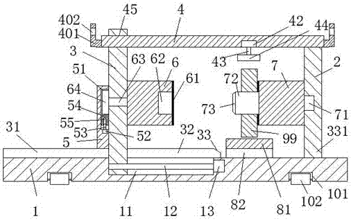
[0021] refer to Figure 1-4 The shown high-efficiency bridge equipment includes a base plate 1 and a fixed plate 2 arranged on the base plate 1. A mounting groove 101 is arranged around the bottom of the base plate 1, and balls 102 are installed in the mounting groove 101. By The ball 102 is convenient to move the base plate 1, and the base plate 1 is also provided with a sliding joint groove 11 on the left side of the fixed plate 2, and the sliding joint frame 3 movable left and right is arranged in the sliding joint groove 11, so that The top of the sliding joint frame 3 is provided with an upward slot 45, and a top plate 4 is movably arranged ...


PUM


Abstract

The invention discloses a high-efficiency bridge equipment, which comprises a bottom plate and a fixing plate arranged on the bottom plate, installation grooves are arranged around the bottom of the bottom plate, balls are installed in the installation grooves, and the bottom plate is located at the The left side of the fixed plate is also provided with a sliding joint groove, the sliding joint frame is provided with a sliding joint frame that can move left and right, the top of the sliding joint frame is provided with an upward groove, and the sliding joint frame is movably provided with a The top plate, the right end of the top plate is fixedly connected with the fixed plate, the left end of the fixed plate is rotatably provided with a right turntable, the right end of the right turntable is rotatably connected with the first electric rotating machine arranged in the fixed plate, The structure of the present invention is relatively simple, the production cost is relatively low, and the operation is relatively simple, which greatly increases the grinding efficiency of cylindrical pipe fittings, reduces the waste of human resources, and has good grinding effect and high grinding precision, which meets the requirements of modern production. need.

Description

technical field [0001] The invention relates to the field of bridges, in particular to high-efficiency bridge equipment. Background technique [0002] In the process of bridge building construction, cylindrical pipe fittings are often used. After being corroded by rainwater or used for a long time, the outer surface of the pipe fittings is easy to burr, so it is necessary to grind the pipe fittings to make the outer surface of the pipe fittings smooth. Due to its shape Particularity, it is difficult to fix the outer ring of cylindrical pipe fittings when grinding, and the general grinding device cannot meet the grinding process of cylindrical pipe fittings. The traditional grinding method of cylindrical pipe fittings is to manually grind cylindrical pipe fittings with sandpaper Grinding, this grinding method is not only inefficient, the grinding quality is poor, but also time-consuming and laborious, which greatly wastes human resources and increases the cost of grinding. Th...

Claims


Application Information

Patent Timeline
Patent Type & Authority Applications(China)
IPC IPC(8): B24B9/00B24B5/04B24B5/35B24B41/06B24B41/02B24B47/14B24B55/12
CPCB24B9/00B24B5/04B24B5/35B24B41/02B24B41/067B24B47/14B24B55/12
Inventor 岑浩明
Owner 岑浩明
Why Eureka
Try Eureka