Foam scrubber
A technology of scrubber and foam, which is applied in the field of foam scrubber, can solve the problems of affecting desulfurization efficiency, reducing desulfurization efficiency, and taking away, so as to reduce secondary pollution, improve removal efficiency, and increase the effect of rapid cooling
- Summary
- Abstract
- Description
- Claims
- Application Information
AI Technical Summary
Problems solved by technology
Method used
Image
Examples
Embodiment 1
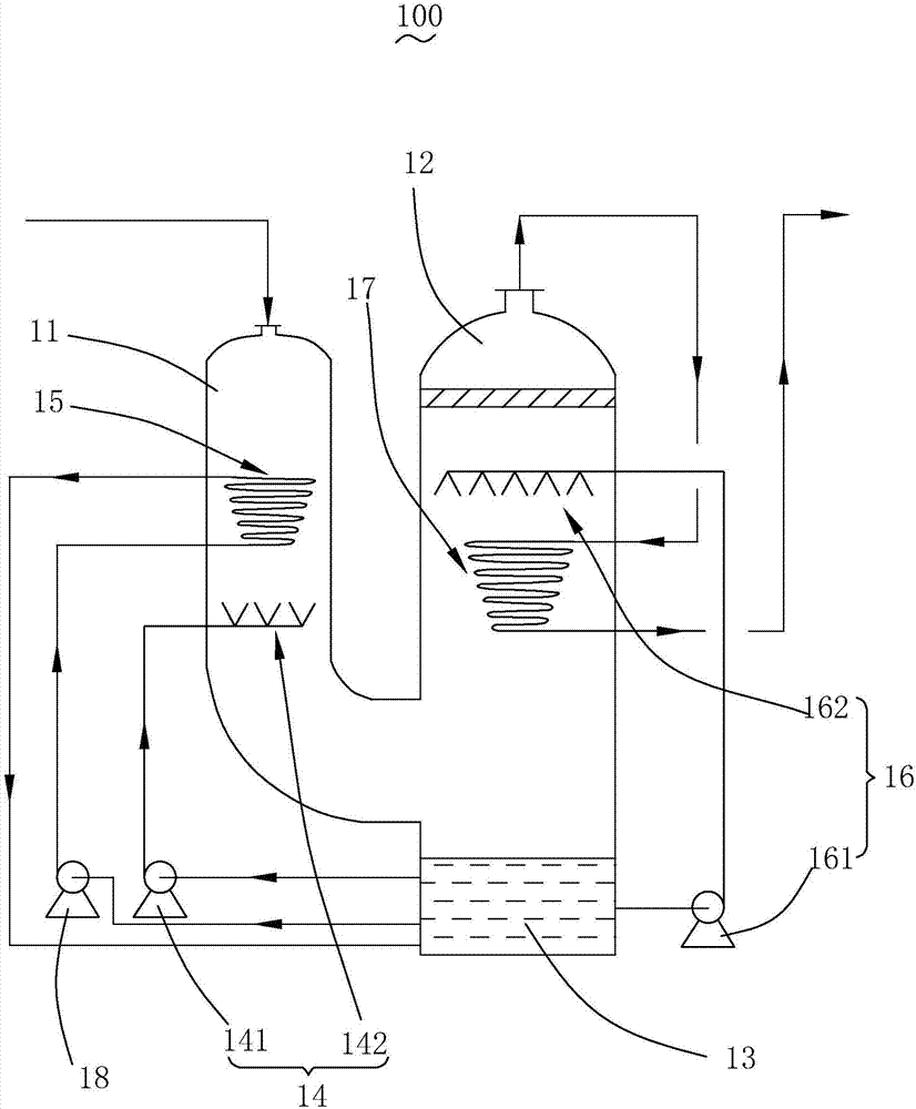
[0036] see figure 1 , is a structural schematic diagram of Embodiment 1 of the foam scrubber provided by the present invention. The foam scrubber 100 includes a washing pipe 11 , a washing tower 12 , a circulating water tank 13 , a first spraying device 14 , a first conical coil 15 , a second spraying device 16 and a second conical coil 17 . The washing pipe 11 communicates with the washing tower 12, and the circulating water tank 13 is arranged at the bottom of the washing tower 12 and communicates with the washing tower 12; the first spraying device 14 is connected with the circulating water tank 13 It is used to spray the flue gas in the washing pipe 11; the first conical coil pipe 15 is arranged in the washing pipe 11, and the inside is filled with a heat exchange medium; the second spraying device 16 and the The circulating water tank 13 is connected to spray the flue gas in the washing tower 12; the second conical coil 17 is arranged in the washing tower 12 and filled w...
Embodiment 2
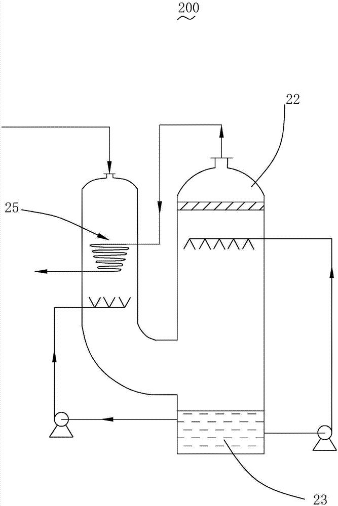
[0052] see figure 2 , is a structural schematic diagram of Embodiment 2 of the foam scrubber provided by the present invention. The foam scrubber 200 is basically the same as the foam scrubber 100 described in Embodiment 1, except that the heat exchange medium in the first conical coil 25 is different.
[0053] Specifically, the inlet end of the first conical coil 25 is connected to the exhaust port of the washing tower 22, and the outlet end of the first conical coil 25 is connected to the outside. That is, the heat exchange medium in the first conical coil 25 is the purified gas discharged from the washing tower 22 .
[0054] In this embodiment, the technical effect of the first conical coil 25 is the same as that in Embodiment 1. Moreover, the foam scrubber 200 has the advantages of less components, less input, and low cost.
[0055] And in the present embodiment, the second conical coil is not provided in the washing tower 22. Of course, in order to further enhance the...
Embodiment 3
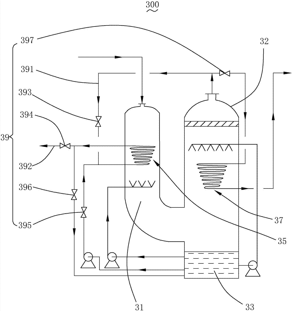
[0057] see image 3 , is a structural schematic diagram of Embodiment 3 of the foam scrubber provided by the present invention. The foam washer 300 is basically the same as the foam washer 100 described in the first embodiment, the difference is that the foam washer 300 further includes a switching device 39 .
[0058] Specifically, the switching device 39 includes a first circulation pipeline 391, a second circulation pipeline 392, a first communication valve 393, a second communication valve 394, a third communication valve 395, a fourth communication valve 396 and a fifth communication valve 397 ,in,
[0059] One end of the first circulation pipeline 391 is connected to the exhaust port of the washing tower 32, and the other end is connected to the inlet end of the first conical coil pipe 35, and the first communication valve 393 is located at the first A circulation pipeline 391;
[0060] One end of the second circulation pipeline 392 is connected to the outlet end of t...
PUM
| Property | Measurement | Unit |
|---|---|---|
| angle | aaaaa | aaaaa |
| distance | aaaaa | aaaaa |
Abstract
Description
Claims
Application Information
 - Generate Ideas
- Intellectual Property
- Life Sciences
- Materials
- Tech Scout
- Unparalleled Data Quality
- Higher Quality Content
- 60% Fewer Hallucinations
Browse by: Latest US Patents, China's latest patents, Technical Efficacy Thesaurus, Application Domain, Technology Topic, Popular Technical Reports.
© 2025 PatSnap. All rights reserved.Legal|Privacy policy|Modern Slavery Act Transparency Statement|Sitemap|About US| Contact US: help@patsnap.com


