
Hydraulic supply device and control method

A technology of hydraulic supply and hydraulic circuit, applied in the direction of transmission control, transmission parts, components with teeth, etc., can solve problems such as increased fuel consumption, increased wear of transmission components, single operating point, etc., and achieves improved shifting. quality effect

Active Publication Date: 2019-03-29
ZF FRIEDRICHSHAFEN AG
View PDF7 Cites 0 Cited by
  • Summary
  • Abstract
  • Description
  • Claims
  • Application Information

AI Technical Summary

Problems solved by technology

It has been found that in the known hydraulic supply devices there is the disadvantage that, by operating the regulating pump sufficiently stably, a single operating point can be determined in the best case
This increases the fuel consumption of the vehicle or causes increased wear on transmission components

Method used


Image

  • Hydraulic supply device and control method

Examples


Embodiment Construction

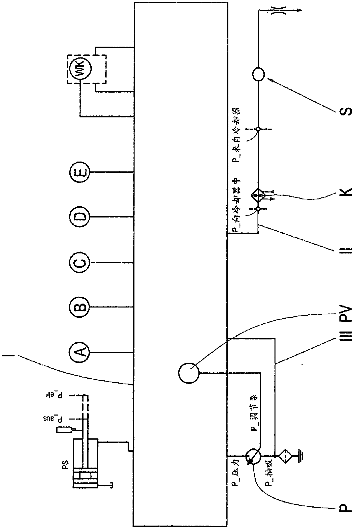
[0023] The supply device comprises a primary hydraulic circuit I for supplying the transmission components, for example shift elements A, B, C, D, E and the hydrodynamic coupling WK, as well as the parking lock PS.

[0024] The shifting elements A to E are supplied with hydraulic pressure via the primary hydraulic circuit I so that they can be engaged or disengaged. Furthermore, the fluid coupling and the parking lock PS are supplied with hydraulic medium in order to be engaged or disengaged by means of the engagement pressure Pein and the disengagement pressure Paus.

[0025] Furthermore, the supply device comprises a secondary hydraulic circuit II, which is supplied with hydraulic medium for lubricating and cooling the transmission components. A cooling device K is provided in the secondary hydraulic circuit II, from which it is supplied with a pressure p_zK, which is measured upstream of the cooler in the direction of flow. The hydraulic medium with the pressure p_vK measu...


PUM


Abstract

The invention relates to a hydraulic supply device in an automatic transmission of a vehicle having a primary hydraulic circuit (I) for supplying transmission components, a secondary hydraulic circuit (II) for lubricating and cooling the transmission components and at least one A pump (P) for generating a delivery volume flow in the hydraulic circuit (I, II); wherein a detection device (S) is provided for detecting the current hydraulic medium volume flow in the secondary hydraulic circuit (II), with to adjust the desired delivery volume flow of the pump (P). Furthermore, the invention relates to a method for actuating a pump of a hydraulic supply device in an automatic transmission of a vehicle, wherein a corresponding current volume of hydraulic medium in a secondary hydraulic circuit (II) for lubricating and cooling transmission components is detected For the flow rate, the volume flow demand is ascertained from the characteristic curve for the current operating range of the automatic transmission, and the delivery volume flow of the pump (P) is actuated as a function of the ascertained volume flow demand.

Description

technical field [0001] The invention relates to a hydraulic supply device in an automatic transmission of a vehicle. Background technique [0002] For example, document US Pat. No. 4,693,081 discloses a method and an actuation system for actuating a hydraulic pump of an automatic transmission. By correspondingly evaluating the throttle valve sensor, the wheel speed sensor and the engine speed sensor, the pump supplying the automatic transmission with hydraulic medium is actuated as a function of the power of the internal combustion engine. The power of the hydraulic pump is essentially predetermined by the engine speed. [0003] For example, DE 10 2004 008 611 A1 to the applicant also discloses the use of a regulating pump as a hydraulic pump for the hydraulic supply of an automatic transmission. It has been found that in the known hydraulic supply devices there is the disadvantage that a single operating point can be determined in the best case by sufficiently stable oper...

Claims


Application Information

Patent Timeline
Patent Type & Authority Patents(China)
IPC IPC(8): F16H61/00F16H57/04
CPCF16H57/0435F16H61/00F16H2061/0037F16H61/0009F16H61/0025F16H57/0436
Inventor A·汉德里希R·布劳恩T·罗泽T·施密特P·席勒F·迈尔
Owner ZF FRIEDRICHSHAFEN AG
Learn More