
Multi-loop self-biasing phase-locked loop circuit and clock generator

A self-bias, multi-loop technology, applied in the direction of electrical components, automatic power control, etc., can solve the problems of dynamically adjusting the parameters of each module and not being able to apply to multiple application systems, and achieve short locking time and wide input and output frequencies Range, effect of strong resistance process

Active Publication Date: 2017-07-21
SHENZHEN STATE MICROELECTRONICS CO LTD
View PDF5 Cites 12 Cited by
  • Summary
  • Abstract
  • Description
  • Claims
  • Application Information

AI Technical Summary

Problems solved by technology

[0004] The purpose of the embodiment of the present invention is to provide a multi-loop self-biased phase-locked loop circuit, aiming to solve the problem that the existing phase-locked loop cannot The working state dynamically adjusts the parameters of each module to output high-performance frequency signals within the entire working range, resulting in the problem that it cannot be applied to multiple application systems

Method used


Image

  • Multi-loop self-biasing phase-locked loop circuit and clock generator
  • Multi-loop self-biasing phase-locked loop circuit and clock generator
  • Multi-loop self-biasing phase-locked loop circuit and clock generator

Examples


Embodiment Construction

[0026] In order to make the object, technical solution and advantages of the present invention clearer, the present invention will be further described in detail below in conjunction with the accompanying drawings and embodiments. It should be understood that the specific embodiments described here are only used to explain the present invention, not to limit the present invention. In addition, the technical features involved in the various embodiments of the present invention described below can be combined with each other as long as they do not constitute a conflict with each other.

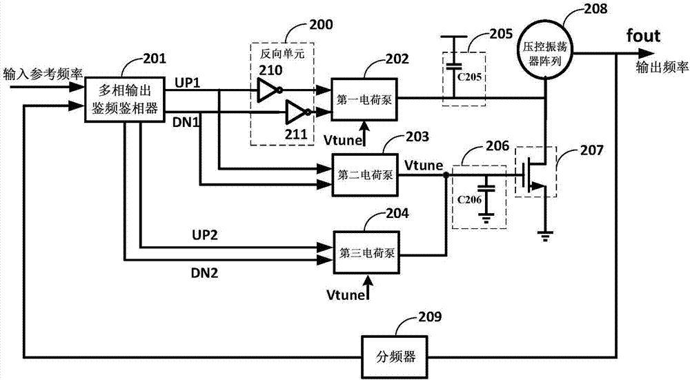
[0027] The multi-loop self-biased phase-locked loop structure provided by the embodiment of the present invention has a fixed ratio of the loop bandwidth to the input reference frequency, and a fixed loop damping factor, so that a wide input and output frequency range, low output clock jitter, and lock time can be achieved. Short, good PVT characteristics and other parameters performance. The p...


PUM


Abstract

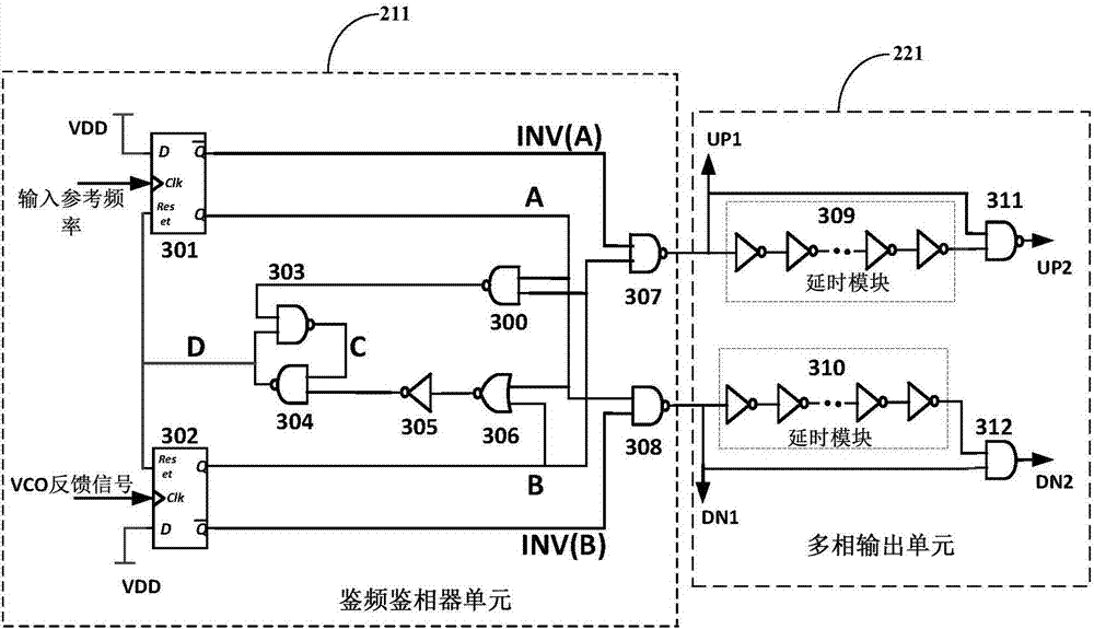
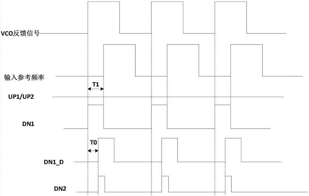
The invention is applicable to the field of integrated circuits, and provides a multi-loop self-biasing phase-locked loop circuit and a clock generator. The circuit comprises a multi-phase output phase frequency detector, a reverse unit, a first charge pump, a second charge pump, a third charge pump, a switch unit, a voltage-controlled oscillator array and a frequency divider, wherein when a frequency difference between a signal output by the frequency divider and input reference frequency is less than a first threshold, the first and second charge pumps work simultaneously, the output current of the first charge pump is used for controlling a voltage-controlled oscillator to work so as to achieve output with a wide frequency range; the second charge pump and the third charge pump forms a control voltage on a second energy storage unit to control the current of the switch unit, so as to achieve dynamic adjustment of a ratio between the current of the chare pump and the current of the voltage-controlled oscillator. The multi-loop self-biasing phase-locked loop circuit provided by the invention has the advantages of being wide in application range, good in transportability, wide in input and output range and free from being affect by PVT, and having extremely strong capacity of resistant to technology, supply voltage and ambient temperature.

Description

technical field [0001] The invention belongs to the field of integrated circuits, in particular to a multi-loop self-bias phase-locked loop circuit and a clock generator. Background technique [0002] Due to the advantages of flexible frequency adjustment and small output signal jitter, phase-locked loops have become an indispensable part of modern integrated circuits. For different applications, the requirements for the performance parameters of the PLL are also different, such as: input and output frequency range, frequency division range, output signal jitter / phase noise, power consumption and area, etc. [0003] However, in the current traditional PLL structure, the parameters of each module are basically fixed, and can only output high-performance frequency signals within a narrow working range, such as a very narrow input and output frequency range and frequency division range. However, expanding the range usually leads to output signal jitter and affects product perf...

Claims


Application Information

Patent Timeline
Patent Type & Authority Applications(China)
IPC IPC(8): H03L7/089H03L7/18
CPCH03L7/0891H03L7/18Y02D30/70
Inventor 刘宝宝宋阳赵鹏
Owner SHENZHEN STATE MICROELECTRONICS CO LTD
Learn More