Eureka AIR delivers breakthrough ideas for toughest innovation challenges, trusted by R&D personnel around the world.

A device for removing fluorine in zinc waste electrolyte

A waste electrolyte, hollow technology, applied in the field of zinc hydrometallurgy, can solve the problems of rare earth consumption, limited effect of fluorine removal, high cost, etc., and achieve the effect of maintaining permeability and preventing settlement

Inactive Publication Date: 2018-11-23
刘向东
View PDF7 Cites 0 Cited by
  • Summary
  • Abstract
  • Description
  • Claims
  • Application Information

AI Technical Summary

Problems solved by technology

[0004] For the fluorine accumulated in the zinc hydrometallurgy solution, there is no very effective method to remove it. An important method used is to use ion exchange resin to partially absorb the fluorine in the solution. On the one hand, the effect of this method is very good. Limited, when the fluorine concentration reaches a relatively low concentration, the ion exchange capacity will be greatly reduced, which cannot meet the requirements of electrowinning (electrolytic) zinc; on the other hand, when the ion exchange resin is saturated and needs to be regenerated, it will produce A large amount of recycled wastewater with high concentration of heavy metals and high acidity is difficult to treat and discharge, and will also cause a large amount of metal loss
Another important method is to add an excessive amount of rare earth salts to the zinc sulfate solution, so that fluorine can be precipitated and removed as a rare earth double salt. This method consumes precious rare earths and is expensive, which limits the use of enterprises.

Method used


Image

  • A device for removing fluorine in zinc waste electrolyte
  • A device for removing fluorine in zinc waste electrolyte
  • A device for removing fluorine in zinc waste electrolyte

Examples


Embodiment 1

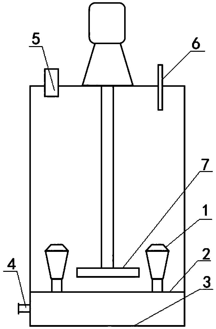
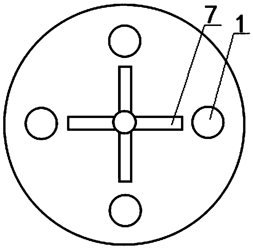
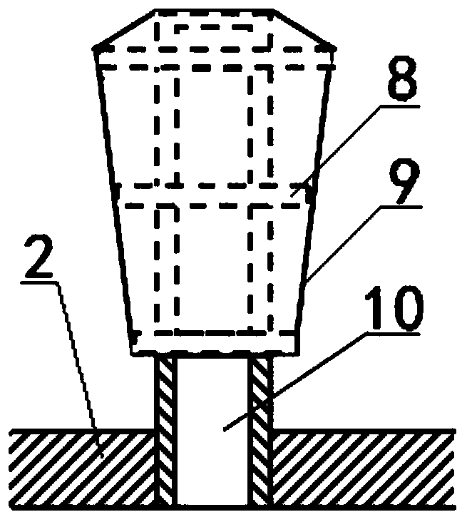
[0024] Such as figure 1 , 2 , 3, a device for removing fluorine in zinc waste electrolyte, comprising a hollow reaction vessel and its waste electrolyte feed port 5 and drain port 4, the top of the hollow reaction vessel is provided with a stirring structure , the waste electrolyte feed inlet 5 and the heating steam pipe 6 that can be stretched into the waste electrolyte surface; An inverted tapered tower column 1 is connected, and the inverted tapered tower column 1 is composed of a pipe with several holes in the pipe wall and a filter screen 9 with a diameter of 0.1mm on the surface of the pipe. The lower bottom layer 3 and the upper bottom layer 2 A liquid outlet 4 is opened on the container wall between; a support ring 8 is provided between the pipe of the inverted tapered column 1 and the filter screen 9; a container wall between the lower bottom 3 and the upper bottom 2 is opened There is a liquid discharge port 4; the stirring structure includes a motor, a reducer and...

Embodiment 2

[0030] Such as figure 1 , 2, 3, a device for removing fluorine in zinc waste electrolyte, comprising a hollow reaction vessel and its waste electrolyte feed port 5 and drain port 4, the top of the hollow reaction vessel is provided with a stirring structure , the waste electrolyte feed inlet 5 and the heating steam pipe 6 that can be stretched into the waste electrolyte surface; An inverted tapered tower column 1 is connected, and the inverted tapered tower column 1 is composed of a pipe with several holes in the pipe wall and a filter screen 9 with a diameter of 0.05mm on the surface of the pipe. The lower bottom layer 3 and the upper bottom layer 2 A liquid outlet 4 is opened on the container wall between; a support ring 8 is provided between the pipe of the inverted tapered column 1 and the filter screen 9; a container wall between the lower bottom 3 and the upper bottom 2 is opened There is a liquid discharge port 4; the stirring structure includes a motor, a reducer and...

Embodiment 3

[0036] Such as figure 1 , 2 , 3, a device for removing fluorine in zinc waste electrolyte, comprising a hollow reaction vessel and its waste electrolyte feed port 5 and drain port 4, the top of the hollow reaction vessel is provided with a stirring structure , the waste electrolyte feed inlet 5 and the heating steam pipe 6 that can be stretched into the waste electrolyte surface; An inverted tapered tower column 1 is connected, and the inverted tapered tower column 1 is composed of a pipe with several holes in the pipe wall and a filter screen 9 with a diameter of 0.03mm on the surface of the pipe. The lower bottom layer 3 and the upper bottom layer 2 A liquid outlet 4 is opened on the container wall between; a support ring 8 is provided between the pipe of the inverted tapered column 1 and the filter screen 9; a container wall between the lower bottom 3 and the upper bottom 2 is opened There is a liquid discharge port 4; the stirring structure includes a motor, a reducer an...


PUM

PropertyMeasurementUnit
pore sizeaaaaaaaaaa
heightaaaaaaaaaa

Abstract

The invention discloses a device for carrying out fluoride removal in a zinc waste electrolyte. The device comprises a hollow reaction vessel, a stirring structure, a waste electrolyte feeding opening and a heating steam pipe capable of stretching into the position below the waste electrolyte face, wherein the stirring structure, the waste electrolyte feeding opening and the heating steam pipe are arranged at the top of the hollow reaction vessel. The hollow reaction vessel is provided with a dual-layer bottom structure. An upper bottom layer and a lower bottom layer of the dual-layer bottom structure communicate with each other through at least one inverted-cone-shaped tower column. Each inverted-cone-shaped tower column is composed of a communicating structure 10 and a filter screen on the surface of the communicating structure 10. A liquid drainage opening is formed in the wall, between the lower bottom layer and the upper bottom layer, of the vessel. By means of the device, the fluoride removal process can be carried out continuously, the waste electrolyte obtained after fluoride removal can pass through the filter screen, the filter screen is not blocked, and the penetration capacity is kept; and after being separated by the filter screen, the waste electrolyte obtained after fluoride removal enters a cavity between the upper bottom layer and the lower bottom layer, fluorions of the waste electrolyte are kept at a proper concentration, and the chemical reaction of the next step is facilitated.

Description

technical field [0001] The invention relates to a device for removing fluorine from the waste electrolyte after zinc electrowinning (zinc electrolysis), which belongs to the technical field of zinc hydrometallurgy, in particular to a device for removing fluorine from zinc waste electrolyte . Background technique [0002] In the wet zinc smelting process, zinc concentrate contains a small amount of fluorine, and other zinc-containing raw materials also contain a small amount of fluorine, and some of these fluorine will dissolve into the zinc hydrosmelting solution along with the smelting process. When the concentration of fluorine reaches a certain level, it will cause serious harm to the zinc electrowinning process, manifested as difficulty in stripping the cathode zinc, corrosion of the cathode plate, etc., which will seriously affect the stability of production and product quality, and increase the production cost of the enterprise. Economic benefit declines. Due to thes...

Claims


Application Information

Patent Timeline
Patent Type & Authority Patents(China)
IPC IPC(8): C25C1/16C25C7/06C22B3/44C22B3/02
CPCC22B3/02C22B3/44C25C1/16C25C7/06Y02P10/20
Inventor 刘向东
Owner 刘向东
Why Eureka
Eureka Blog
Learn More