
Method and device for assisting supersonic vibration in laser cladding

A technology of ultrasonic vibration and auxiliary laser, which is applied in the field of laser processing to achieve the effect of simple structure, quality assurance and convenient operation

Pending Publication Date: 2017-07-04
JIANGSU UNIV OF TECH
View PDF7 Cites 19 Cited by
  • Summary
  • Abstract
  • Description
  • Claims
  • Application Information

AI Technical Summary

Problems solved by technology

[0004] The technical problem to be solved by the present invention is: in order to solve the problems existing in the prior art that ultrasonic waves are introduced into the laser molten pool along the vertical interval and directly into the laser melting pool, a method and device for ultrasonic vibration-assisted laser cladding are now provided, which uses ultrasonic waves along the The horizontal direction is indirectly introduced into the laser molten pool to ensure the quality of the laser cladding parts. The self-contained cooling system is used to cool the horn, reduce the heat transmitted to the transducer, and ensure the work of the transducer by changing the flow rate of the coolant. Within the allowable temperature range, so as to ensure that the laser cladding process can be carried out for a long time, improve the efficiency of the laser cladding process, and prolong the service life of the transducer

Method used


Image

  • Method and device for assisting supersonic vibration in laser cladding
  • Method and device for assisting supersonic vibration in laser cladding
  • Method and device for assisting supersonic vibration in laser cladding

Examples


Embodiment 1

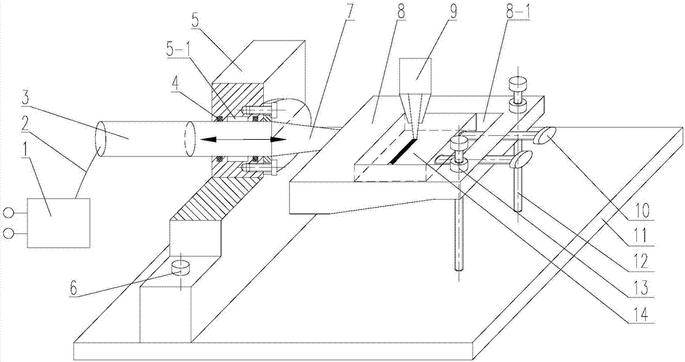
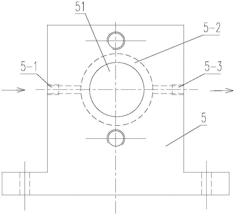
[0036] Such as figure 1 with 2 As shown, a device for ultrasonic vibration assisted laser cladding, the device includes a base 11, an ultrasonic vibration system, a support 5 and a supporting plate 8;

[0037] The ultrasonic vibration system includes an ultrasonic generator 1 for outputting ultrasonic frequency current, a transducer 3 for converting ultrasonic frequency current into mechanical vibration, and a horn 7 for increasing the amplitude of mechanical vibration. The ultrasonic generator 1 passes The cable 2 is connected to the transducer 3, and the transducer 3 is fixedly connected to the horn 7;

[0038] The support 5 is fixed on the base 11 through the fixing screw 6, and the horn 7 is fixed on the support 5;

[0039] The upper surface of the supporting plate 8 is provided with a prefabricated groove 8-1 for placing the cladding part 14, and the end of the horn 7 away from the transducer 3 is fixedly connected with the supporting plate 8, and the upper part of the ...

Embodiment 2

[0049] A method for ultrasonic vibration-assisted laser cladding, the method is that the laser beam transmitted by the laser cladding head 9 is irradiated on the cladding part 14 along the vertical direction, and at the same time, the ultrasonic vibration acts indirectly on the laser molten pool along the horizontal direction, A cladding layer is formed on the cladding part 14 , where the laser cladding head 9 irradiates on the cladding part 14 , and a laser molten pool will be formed on the irradiated area on the upper surface of the cladding part 14 .

[0050] Specifically, the steps of the method are:

[0051] a. First, after the cladding part 14 is polished, it is ultrasonically cleaned with acetone, and then dried with hot air;

[0052] b. Then fix the pretreated cladding part 14 in the prefabricated groove 8-1 of the supporting plate 8, and apply coupling agent on the bonding surface of the cladding part 14 and the supporting plate 8;

[0053] c. Dry the cladding powder...

Embodiment 3

[0056] Taking the laser cladding of titanium alloy plate as an example, the above method of ultrasonic vibration assisted laser cladding is explained:

[0057] First prefabricate a 45mm×12mm×1mm slot on a 62.5mm×60mm×10mm TC4 titanium alloy plate, polish it with sandpaper, then use acetone to ultrasonically degrease it for 15 minutes, then dry it with hot air, and put the pretreated TC4 titanium alloy plate Put it in the prefabricated groove 8-1 of the supporting plate 8, and press it with the compression screw 10, and apply coupling agent on the bonding surface of the two;

[0058] The laser cladding powder is TC4 titanium alloy spherical powder with a particle size of 75-120 μm. Before cladding, the titanium alloy powder must be dried under vacuum conditions at about 110 ° C to prevent pores in the cladding layer;

[0059] The output frequency of ultrasonic generator 1 is set to 38KHz. The 4Kw fiber laser processing system consists of YLS-4000 fiber laser, TWIN PF 2 / 2-MF pow...


PUM


Abstract

The invention relates to the technical field of laser processing, in particular to a method and a device for assisting supersonic vibration in laser cladding. The method comprises the following steps: a laser beam conducted by a laser cladding head is radiated to a cladding element along a vertical direction, meanwhile, the supersonic vibration indirectly acts in a laser molten pool along a horizontal direction, and a cladding layer is formed on the cladding element. The device comprises a base, a supersonic vibration system, a support and a supporting plate, wherein the supersonic vibration system comprises a supersonic wave generator, an energy converter and an amplitude-change pole used for enhancing a mechanical vibration amplitude; the supersonic wave generator is connected with the energy converter through a cable; the energy converter is fixedly connected with the amplitude-change pole. According to the method, an additionally adding energy field, i.e., supersonic vibration which is horizontally introduced, is used for improving the tissue and the performance of the laser cladding layer, and cooling water is introduced into a cooling water tank to lower heat transferred to the energy converter in a laser cladding process so as to improve the production efficiency of laser cladding processing. The device has the advantages of simple structure, convenience in operation, long service life and the like.

Description

technical field [0001] The invention relates to the technical field of laser processing, in particular to a method and device for ultrasonic vibration-assisted laser cladding. Background technique [0002] Laser cladding technology has the characteristics of controllable heat input, fast cooling and metallurgical bonding with the substrate, so it has important application value in aerospace, automobile, mold, medical and chemical industries. However, on the one hand, the cladding layer has residual tensile stress due to uneven cooling; on the other hand, due to the high temperature of the molten pool, the grains of the cladding layer are coarse; in addition, defects such as pores and cracks also appear in the cladding layer. At present, these shortcomings limit the vigorous promotion and application of laser cladding technology. [0003] At present, scholars at home and abroad have used an external ultrasonic vibration energy field to solve the problems existing in laser cl...

Claims


Application Information

Patent Timeline
Patent Type & Authority Applications(China)
IPC IPC(8): C23C24/10
CPCC23C24/106
Inventor 葛茂忠范真杨晓红朱福先杨超卢雅琳杨林吉庭婷杨刚
Owner JIANGSU UNIV OF TECH
Learn More