
Automatic deburring machine for engine camshaft

A technology for deburring machines and camshafts, which is applied to grinding drive devices, parts of grinding machine tools, and machine tools suitable for grinding the edge of workpieces, etc. It can solve the problem of difficult removal of burrs on both sides of the cam and switching of chip wheel brushes Long time, not suitable for mass production, etc., to achieve good deburring effect, save installation time, and small machine tool footprint

Inactive Publication Date: 2017-05-31
魏显懿
View PDF8 Cites 4 Cited by
  • Summary
  • Abstract
  • Description
  • Claims
  • Application Information

AI Technical Summary

Problems solved by technology

This method can only remove the burrs one by one, the production efficiency is low, and it is not suitable for mass production
At the same time, the deburring effect of the disc wheel brush is not good, the burrs on both sides of the cam are not easy to remove, and there are many residual burrs
In addition, the switching time of the chip wheel brush is long, and the machine tool occupies a large area

Method used


Image

  • Automatic deburring machine for engine camshaft
  • Automatic deburring machine for engine camshaft

Examples


Embodiment Construction

[0021] The present invention will be further described in detail below in conjunction with the accompanying drawings.

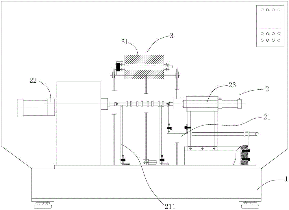
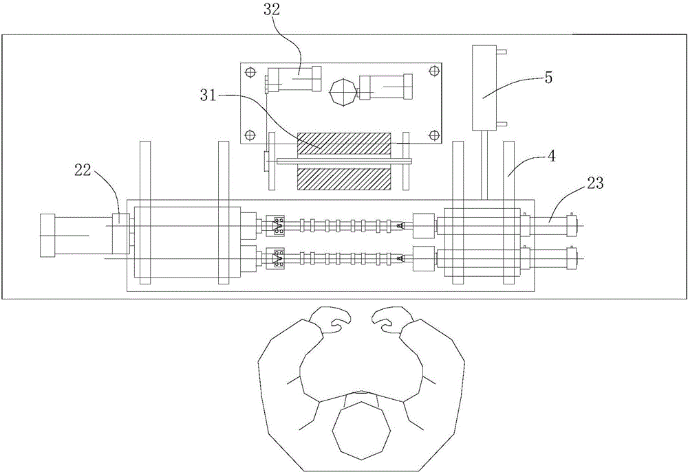
[0022] During specific implementation: if figure 1 and figure 2 As shown, an engine camshaft automatic deburring machine includes a base 1, a cam clamping mechanism 2 and a burr removal mechanism 3 are arranged on the base 1, the cam clamping mechanism 2 includes a frame body 21, and a set The rotary driving device 22 and the tailstock tightening device 23 on the frame body 21, the tailstock tightening device 23 includes a push rod capable of extending and contracting in the axial direction, and the push rod of the tailstock tightening device 23 is connected to the The rotary output shafts of the rotary driving device 22 are relatively and coaxially arranged, and the maximum distance between the two is greater than the length of the camshaft to be deburred, and the minimum distance is less than the length of the camshaft to be deburred; the deburring mechan...


PUM


Abstract

The invention discloses an automatic deburring machine for an engine camshaft. The automatic deburring machine comprises a base, wherein a camshaft clamping mechanism and a deburring mechanism are arranged on the base; the camshaft clamping mechanism comprises a frame body, as well as rotary driving devices and tailstock jacking devices, which are arranged on the frame body; jack rods of the tailstock jacking devices and rotary output shafts of the rotary driving devices are oppositely and coaxially arranged; the deburring mechanism comprises an abrasive wire brush roller and a driving motor used for driving the abrasive wire brush roller to rotate; and the abrasive wire brush roller is parallel to the jack rods of the tailstock jacking devices and the rotary output shafts of the rotary driving devices. The automatic deburring machine for the engine camshaft has the advantages that the occupation is small, the deburring effect is good, the production efficiency is high, and batch production can be easily realized.

Description

technical field [0001] The invention relates to the field of processing engine parts, in particular to an automatic engine camshaft deburring machine. Background technique [0002] After the camshaft of an automobile engine is processed, there are burrs on the surface that need to be removed. The existing deburring method usually uses a servo motor driven by a modified ordinary grinder / lathe to remove the burrs cam by cam. This method can only deburr cams one by one, the production efficiency is low, and it is not suitable for mass production. At the same time, the deburring effect of the disc wheel brush is not good, and the burrs on both sides of the cam are not easy to remove, and there are many residual burrs. In addition, the switching time of the chip wheel brush is long, and the machine tool occupies a large area. Contents of the invention [0003] Aiming at the deficiencies of the above-mentioned prior art, the technical problem to be solved by the present invent...

Claims


Application Information

Patent Timeline
Patent Type & Authority Applications(China)
IPC IPC(8): B24B9/04B24B19/12B24B41/06B24B47/12B24B55/04
CPCB24B9/04B24B19/12B24B41/061B24B47/12B24B55/04
Inventor 魏显懿
Owner 魏显懿
Learn More