
Method and system for wide view field micro-imaging based on FPM

A technology of microscopic imaging and wide field of view, applied in microscopes, instruments, optics, etc., can solve problems such as increasing hardware control difficulty, increasing computational complexity, and cell disadvantage, reducing the number of LED exposures and data collection. time, the effect of improving imaging efficiency

Active Publication Date: 2017-05-24
TSINGHUA UNIV
View PDF5 Cites 2 Cited by
  • Summary
  • Abstract
  • Description
  • Claims
  • Application Information

AI Technical Summary

Problems solved by technology

Under these conditions, it generally takes about 3 minutes to use traditional acquisition techniques, which is very unfavorable for observing the dynamic behavior of cells
[0005] In related technologies, two types of strategies are mainly used to improve the acquisition time of FPM: one is to obtain the importance information of different positions of the spectrum through pre-estimation of samples, and perform directional exposure for angles containing important information, and less important for unimportant positions. Exposing or not exposing, thereby reducing the total number of exposures and increasing the acquisition rate, but the main problem is that the pre-estimation of the sample is required, which will not only increase the amount of calculation in the acquisition process, but may not even be able to collect continuously, and each time each LED Different exposure sequences will also increase the difficulty of hardware control; another method is to encode based on LEDs at different positions, encoding LEDs covering different positions in the frequency domain into a group, and exposing at the same time, although it can reduce the exposure of a single LED At the same time, it also reduces the total number of exposures, but its biggest problem is the lack of robustness. First, it cannot guarantee that all samples will be restored according to the given encoding method. Second, this method is too sensitive to system parameters. Sensitive, the change of system parameters will have a great impact on the encoding method and imaging effect

Method used


Image

  • Method and system for wide view field micro-imaging based on FPM
  • Method and system for wide view field micro-imaging based on FPM
  • Method and system for wide view field micro-imaging based on FPM

Examples


Embodiment Construction

[0029] Embodiments of the present invention are described in detail below, examples of which are shown in the drawings, wherein the same or similar reference numerals designate the same or similar elements or elements having the same or similar functions throughout. The embodiments described below by referring to the figures are exemplary and are intended to explain the present invention and should not be construed as limiting the present invention.

[0030] The FPM-based wide-field microscopic imaging method and system according to the embodiments of the present invention will be described below with reference to the accompanying drawings. First, the FPM-based wide-field microscopic imaging method according to the embodiments of the present invention will be described with reference to the accompanying drawings.

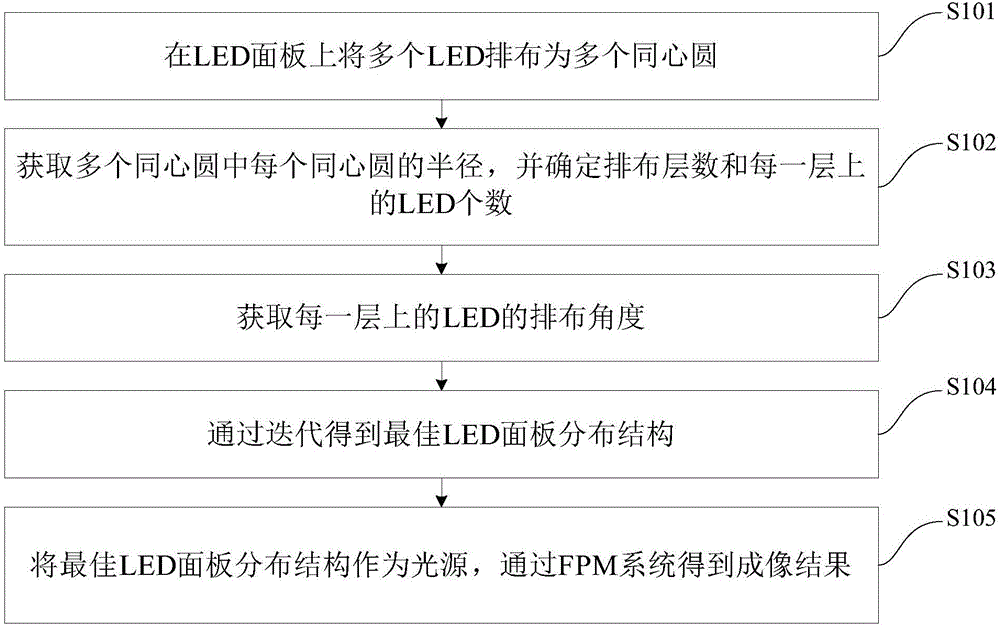
[0031] figure 1 It is a flow chart of the FPM-based wide-field microscopic imaging method of the embodiment of the present invention.

[0032] Such as figure 1 As...


PUM


Abstract

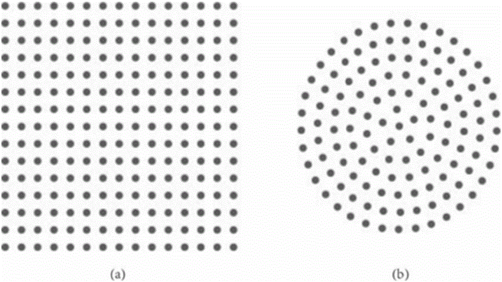
The invention discloses a method and system for wide view field micro-imaging based on FPM. The method comprises the following steps: arranging a plurality of LEDs as a plurality of concentric circles on an LED panel; acquiring a radius of each concentric circle in the plurality of concentric circles and confirming the quantity of arranged layers and the quantity of the LEDs in each layer; acquiring the arranging angles of the LEDs in each layer; iterating, thereby acquiring an optimal LED panel distribution structure; taking the optimal LED panel distribution structure as a light source; and acquiring an imaging result through a frequency domain laminating splicing microscope FPM system. According to the method, a circular LED array is introduced, so that the exposure times are reduced, the imaging efficiency is increased, and the method is simple and is easily realized.

Description

technical field [0001] The invention relates to the technical field of computational imaging, in particular to an FPM-based wide-field microscopic imaging method and system. Background technique [0002] Due to the limited amount of information that the objective lens can transmit, its SBP (space-bandwidth product) will be limited, and SBP is the product of the field of view and the square of the spatial resolution, so wide field of view and high resolution cannot be balanced. [0003] FPM (Fourier Ptychographic Microscopy, frequency-domain laminated mosaic microscopy) technology utilizes interdisciplinary knowledge, applies the knowledge of information technology to traditional microscopy technology, and breaks through the limitation of space-bandwidth product. The specific method is: using the property that the lens is a low-pass filter in the Fourier domain, the pictures obtained by the incident light at different angles correspond to the information of different position...

Claims


Application Information

Patent Timeline
Patent Type & Authority Applications(China)
IPC IPC(8): G02B21/06
CPCG02B21/06
Inventor 戴琼海陈星晔吴嘉敏
Owner TSINGHUA UNIV
Learn More