Magnetic conversion engine

A technology of engines and rotors, applied in the direction of generators/motors, electrical components, etc., can solve the problem that the fundamental defects of DC motors and AC motors have not been truly eliminated, and achieve good dynamic response, high ratio, and flexible and convenient control Effect

Inactive Publication Date: 2017-03-22
高宗大
View PDF6 Cites 1 Cited by
  • Summary
  • Abstract
  • Description
  • Claims
  • Application Information

AI Technical Summary

Problems solved by technology

[0005] However, the above-mentioned improvements are all tinkering with the existing motor structure and operation mode, and the fundamental defects of the above-mentioned DC motors and AC motors have not been truly eliminated.

Method used


Image

  • Magnetic conversion engine
  • Magnetic conversion engine
  • Magnetic conversion engine

Examples


Embodiment Construction

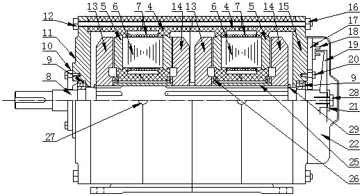
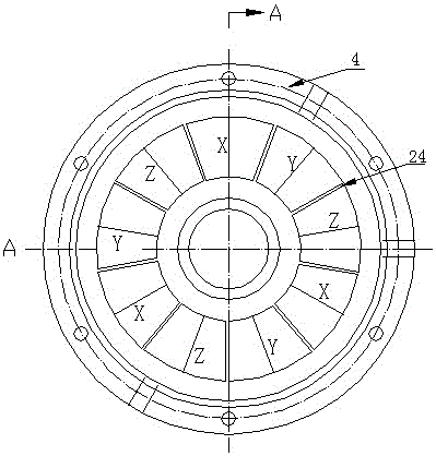
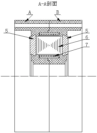
[0030] The overall structure of the magnetic conversion motor of the present invention is as follows: figure 1 1 is the permanent magnet, 2 is the soft magnetic pole, 3 is the notch of the rotor pole, 4 is the stator, 5 is the additional magnetic pole of the stator core, 6 is the iron core, 7 is the winding coil, 8 is the spline shaft, 9 is Bearing, 10 is the bearing end cover, 11 is the left end cover, 12 is the bolt, 13 is the left rotor, 14 is the right rotor, 15 is the right end cover, 16 is the nut, 17 is the photoelectric device fixing plate, 18 is the photoelectric device, 19 is a light interceptor, 20 is a fastening bolt of a photoelectric device fixing plate, 21 is a washer, 22 is a protective cover, 23 is a gap between a soft magnetic pole and a permanent magnetic pole, 24 is a gap between an additional magnetic pole of an iron core, and 25 is a Positioning sleeve, 26 is the thrust bearing, 27 is the lead wire hole, 28 is the fastening bolt of the light cutter, 29 is...


PUM


Abstract

The invention relates to a magnetic conversion engine, and particularly to the magnetic conversion engine which realizes conversion of magnetic energy to mechanical energy by means of interaction between electromagnetic energy and permanent magnetism and interaction between the permanent magnetism and induced electric current. The magnetic conversion engine is characterized in that an electromagnetic torque can be generated in energizing an energizing winding by the magnetic conversion engine; one phase winding is in a power generating state; the direction of an induced electric current magnetic field is same with that of a winding energizing magnetic field; and the induced electric current magnetic field can generate a torque. Therefore, in energizing the phase winding by the magnetic conversion engine, two torques are simultaneously generated, namely an electromagnetic torque, and the torque which is generated by the induced electric current magnetic field, wherein the induced electric current must be used for purposes such as charging a battery; and mechanical efficiency is remarkably improved. The magnetic conversion engine is suitable for an electric vehicle and can perform charging on the battery in operation. On the condition that the electric vehicle performs speed reduction, the mechanical energy can be used for charging the battery and reducing vehicle speed. Freewheeling current in a power converter can be used for charging the battery. The magnetic conversion engine is particularly suitable for charging the battery by means of free inertia which does not generate a braking torque in driving of the electric vehicle in a highway, thereby realizing no requirement for energy supplement of the battery by an external power supply. The electric vehicle is not limited by a driving distance and battery capacity can be reduced. If the electric energy which is generated by a power generating winding is directly fed back to the energizing winding by means of half-wave rectification characteristic of a diode, the magnetic conversion engine similarly can generate a torque, thereby realizing higher suitability for driving of the electric vehicle on the highway. The magnetic conversion engine belongs to new energy technology and new energy vehicle technology.

Description

technical field [0001] The invention relates to a motor, in particular to a magnetic conversion motor which realizes the conversion of magnetic energy into mechanical energy through the interaction between electromagnetic and permanent magnet, and between permanent magnet and induced current. It belongs to the field of motor technology. Background technique [0002] The motor is an energy conversion device commonly used to realize the mutual conversion of electric energy and mechanical energy, and has been widely used in every field of life and life. Since the development of modern motor technology for more than 100 years, the technology has become increasingly mature, and the types are constantly being introduced. In addition to traditional transformers, DC motors, synchronous AC motors, and asynchronous AC motors, stepping motors and reluctance motors have also been developed in recent years. Motors, linear motors and other new motors. [0003] At present, with the conti...

Claims


Application Information

Patent Timeline
Patent Type & Authority Applications(China)
IPC IPC(8): H02N11/00
CPCH02N11/006H02N11/008
Inventor 不公告发明人
Owner 高宗大
Why Eureka
Try Eureka